System and method for measuring temperature of friction pair of wet clutch

A wet clutch and temperature measurement technology, applied in the direction of machine gear/transmission mechanism testing, etc., can solve the problems that the predicted value cannot fully represent the actual temperature value, it is not applicable to measure the temperature of the wet clutch, and the wet clutch has no absolute reliability. Achieve the effects of easy implementation, ensuring high-speed and accurate transmission, and preventing failures

Active Publication Date: 2015-09-30
BEIJING INFORMATION SCI & TECH UNIV
View PDF7 Cites 13 Cited by
  • Summary
  • Abstract
  • Description
  • Claims
  • Application Information

AI Technical Summary

Problems solved by technology

In the patent document with the publication number CN103967963A, a method for measuring the temperature of the DCT wet clutch based on neural network prediction is introduced, but this method only obtains the predicted value of the actual temperature of the wet dual clutch, and the predicted value cannot fully represent the actual temperature. value, and the predicted value does not have absolute confidence for the study of wet clutches
In the document "Experimental Device for Transient Temperature Measurement of Dry Clutch Friction Plate Surface", infrared temperature sensors and collector rings are used to measure the transient temperature of the friction surface of dry clutches. Although the device has a fast response speed and can measure any working condition However, because the interference of oil on the surface of the wet clutch will cause the instability of the infrared temperature sensor, this device is not suitable for measuring the temperature of the wet clutch

Method used


Image

  • System and method for measuring temperature of friction pair of wet clutch
  • System and method for measuring temperature of friction pair of wet clutch
  • System and method for measuring temperature of friction pair of wet clutch

Examples


Embodiment Construction

[0019] The present invention will be described in detail below in conjunction with the accompanying drawings and embodiments.

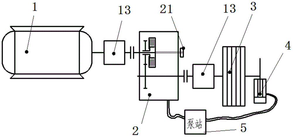
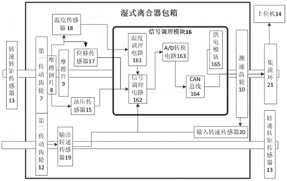
[0020] Such as figure 1 , figure 2 As shown, the present invention provides a wet clutch friction pair temperature measurement system, which includes a power transmission system and a data acquisition system. The power transmission system includes a motor 1, a wet clutch case 2, an adjustable inertia group 3, a hydraulic pressure Brake 4 and a pumping station 5; Among them, the wet clutch box 2 adopts a double-shaft clutch, which is provided with a first transmission shaft 6, a first transmission gear 7, a friction steel plate 8, a friction plate 9, a speed measuring gear 10, a first The two transmission shafts 11 and the second transmission gear 12, and the first transmission shaft 6 and the second transmission shaft 11 all adopt a hollow shaft structure, and the central holes of the shafts are used for arranging data transmission lines in the data...


PUM


Abstract

The invention relates to a system and a method for measuring the temperature of a friction pair of a wet clutch. A motor output shaft of a power transmission system is connected with an input end of a first transmission shaft of a wet clutch box, a first transmission gear is arranged at the input end of the first transmission shaft, a steel friction plate and a friction plate are sequentially arranged at the input end of the first transmission shaft, and a speed measuring gear is arranged at an output end of the first transmission shaft; the first transmission gear is meshed with a second transmission gear arranged on a second transmission shaft, power is transmitted to the second transmission shaft through the second transmission gear, and an output end of the second transmission shaft is sequentially connected with an adjustable inertia group and a hydraulic brake; a pump station is located between the wet clutch box and the hydraulic brake; a motor is used as a power source to output the rotating speed and the torque, and the wet clutch box controls output and cutting off of the power of the second transmission shaft in the wet clutch box. The system and the method effectively solve the problem about measurement of the temperature of the friction pair of the wet clutch in a high-speed rotating state and realize prevention of failures of the wet clutch and real-time accurate detection of the combination state.

Description

technical field [0001] The invention relates to the field of wet clutch dynamic characteristic measurement, in particular to a wet clutch friction pair temperature measurement system and measurement method. Background technique [0002] The wet clutch is a clutch with oil cooling and lubrication on the surface of the friction pair. The oil can take away the heat generated during the coupling process of the clutch at any time. Compared with the dry clutch, it has less wear, longer working life, simple control, smooth engagement, and torque capacity. Large, stable performance, low noise and many other advantages. With its good control performance and heat dissipation, wet clutches are widely used in many tracked vehicles and construction machinery. As a key component in the comprehensive transmission device, the wet clutch realizes power transmission and cut-off through the combination and separation of friction plates and steel plates. In the process of clutch engagement, d...

Claims


Application Information

Patent Timeline
Patent Type & Authority Applications(China)
IPC IPC(8): G01M13/02
Inventor 李乐王立勇周全建
Owner BEIJING INFORMATION SCI & TECH UNIV
Why Eureka
Try Eureka