
Novel pressure-changing and position-changing mechanical ventilation system

A mechanical ventilation and displacement technology, applied in the field of mechanical medical treatment, can solve problems such as difficulty, dynamic overfilling, low blood pressure weaning, etc., and achieve the effects of improving respiratory tidal volume, simple structure and low cost

Inactive Publication Date: 2015-10-07
贾洁
View PDF6 Cites 0 Cited by
  • Summary
  • Abstract
  • Description
  • Claims
  • Application Information

AI Technical Summary

Problems solved by technology

However, positive pressure ventilation also has disadvantages such as ventilator-associated pneumonia, lung injury, dynamic overfilling, hypotension, and difficulty in weaning, which makes this technology bring more serious harm to patients while achieving the function of breathing maintenance. life threatening
With the rapid development of human material civilization and spiritual civilization, human beings are no longer required to save and preserve lives as in the past, but to pursue safe, minimally invasive or non-invasive treatment, and no sequelae. In order to meet the development requirements, many people We have been working on the improvement and perfection of positive pressure ventilation technology, but due to the defects of positive pressure ventilation technology, these improved methods have not achieved obvious results, so everyone is looking for a safer and more effective new mechanical ventilation method

Method used


Image

  • Novel pressure-changing and position-changing mechanical ventilation system
  • Novel pressure-changing and position-changing mechanical ventilation system
  • Novel pressure-changing and position-changing mechanical ventilation system

Examples


Embodiment Construction

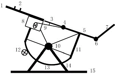
[0030] figure 1 It is a schematic diagram of the overall structure of the ventilation system, including a rotating bed body, a rotating bracket, a floor bracket, and a circuit control and driving unit. plate (3), abdomen supporting plate rotating shaft (4), abdominal leg supporting plate (5), calf supporting plate rotating shaft (6) and calf supporting plate (7), and the head surface support pillow (2) is installed on the head and chest support On the board (1), the abdomen support plate shaft (4) is connected between the abdomen support plate (3) and the abdomen leg support plate (5), and the leg support plate rotation shaft (6) is connected to the abdomen leg support plate Between the plate (5) and the calf support plate (7); the rotating bracket includes a fixed frame rotating shaft (10), a bed body fixing frame (11) and an arc wheel (13), and the rotating shaft (10) passes through The four metal arms are connected with the bed body fixing frame (11), and the bed body fixi...


PUM


Abstract

The invention discloses a novel pressure-changing and position-changing mechanical ventilation system. The novel pressure-changing and position-changing mechanical ventilation system comprises a rotation bed body, a rotation support, a floor stand and a circuit control and driving unit, wherein the rotation bed body comprises a head and chest supporting board (1), a head and face supporting pillow (2), an abdomen supporting board (3), an abdomen supporting board rotating shaft (4), an abdomen and leg supporting board (5), a shank supporting board rotating shaft (6) and a shank supporting board (7); the rotation support comprises a fixing support rotating shaft (10), a bed body fixing support (11) and an arc-shaped wheel (13); the floor stand comprises a supporting foot stool (14) and a supporting bottom support (15); and the circuit control and driving unit comprises a circuit control cabinet (8), a rocking bar driving unit (9) and a motor driving wheel (12). The mechanical ventilation system is simple in structure and low in cost; and a method for changing the position along with breathing synchronously and conducting inclined prone position suspended abdomen pressure changing is ingeniously used, and the breathing potential of the diaphragm muscle is sufficiently aroused and realized under the effects of gravity and inertia force, so that the effectiveness of a transverse diaphragm in the breathing process is sufficiently used, and the breathing tidal volume is improved.

Description

technical field [0001] The invention belongs to the field of mechanical medical technology, and in particular relates to a novel pressure-variable-displacement mechanical ventilation system, which is a non-invasive mechanical ventilation device for treating patients with dyspnea, respiratory distress syndrome (ARDS) and acute respiratory failure. , the device combines two assisted breathing modes of synchronous displacement and variable pressure to complete non-invasive and efficient ventilation. Background technique [0002] As an important medical instrument, the ventilator's control method is related to the safety and comfort of patients, as well as the reliability and timeliness of treatment. Therefore, it is particularly important to choose a reasonable control mode of the ventilator system. In recent years, with the application of computer technology, the intelligent control technology in ventilator research has developed rapidly. Mastering and using the intelligent ...

Claims


Application Information

Patent Timeline
IPC IPC(8): A61H31/02
Inventor 万一品贾洁宋绪丁
Owner 贾洁
Learn More