Clamping device of machine tool

A clamping device and machine tool technology, which is applied in the field of machinery, can solve problems affecting production efficiency, increase operating time, and increase production costs, and achieve the effects of improving production efficiency, avoiding safety accidents, and reducing labor intensity

Active Publication Date: 2015-10-07
台州中弈智能装备有限公司
View PDF7 Cites 9 Cited by
  • Summary
  • Abstract
  • Description
  • Claims
  • Application Information

AI Technical Summary

Problems solved by technology

[0004] The disadvantage of such a technical solution is that it is necessary to manually clamp and loosen the workpiece, such as turning the lever on the chicken heart chuck, and then clamping the workpiece before processing
In this way, due to the manual operation of the fixture and the manual clamping of the workpiece, the working time is greatly increased, and sometimes the installation time will exceed the machining time, which greatly affects the production efficiency and increases the production cost.

Method used


Image

  • Clamping device of machine tool
  • Clamping device of machine tool
  • Clamping device of machine tool

Examples


Embodiment 1

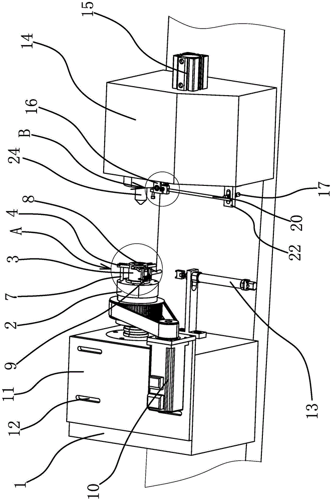
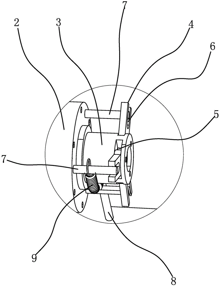
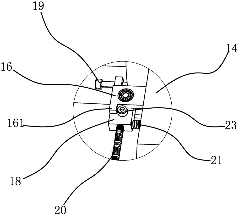
[0032]The clamping device includes a mounting base 1, a rotating head frame 2, a rotating cylinder 3, a clip 4, a clamping part 41, a through groove 5, an opening groove 6, a fixed shaft 7, a toggle member 8, a tension spring 9, a servo Motor 10, mounting plate 11, sliding hole 12, cylinder 13, tailstock 14, tailstock cylinder 15, bracket one 16, limit protrusion 161, bracket two 17, connecting plate 18, detection screw 19, adjusting rod 20, reset Spring 21, sensor 22, limit screw 23, thimble 24.

[0033] Specifically, as figure 1 As shown, the clamping device includes a mounting base 1 and a rotating head frame 2. The rotating head frame 2 is axially positioned on the mounting base 1 and can rotate circumferentially relative to the mounting base 1 driven by a driving source. The driving source is a servo motor 10 , the upper surface of the mounting base 1 is provided with a mounting plate 11, the mounting plate 11 is provided with a sliding hole 12, and the sliding hole 12 i...

Embodiment 2

[0041] The technical solution in this embodiment is basically the same as the technical solution in Embodiment 1, the difference is that in this embodiment, the clamping reset member is a torsion spring, and the torsion spring is sleeved on the fixed shaft 7, and one end of the torsion spring It is fixed on the rotating head frame 2, and the other end of the torsion spring is fixed on the toggle member 8 by a steel wire stay cord, and the tightening direction of the torsion spring is the same as the rotation direction when the workpiece is processed.

Embodiment 3

[0043] The technical solution in this embodiment is basically the same as the technical solution in Embodiment 1. The difference is that in this embodiment, the driving part is a forward and reverse motor, and a push rod is fixedly connected to the motor shaft of the forward and reverse motor. The push rod can abut on the dial 8 and push the dial 8 to make the inner ends of the clips 4 away from each other.


PUM


Abstract

The invention provides a clamping device of a machine tool and belongs to the technical field of machines. The clamping device of the machine tool solves the problem of automatic clamping or loosening of workpieces. The clamping device comprises a mounting base and a rotating headstock, a rotating drum coaxial with the rotating headstock is arranged at the end of the rotating headstock, two or three sheet-shaped clamping sheets are hinted to the rotating drum, through grooves corresponding to the clamping sheets in a one-to-one mode are formed in the periphery of the wall of the rotating drum, the clamping sheets are arranged in the through grooves in a penetrating mode and can swing in the through grooves, open slots are formed in the outer ends, stretching out of the rotating drum, of the clamping sheets, fixing shafts are arranged in the open slots in a penetrating mode, the fixing shafts are fixed to the rotating headstock, the clamping sheets can swing relative to the fixing shafts to enable the inner ends of the clamping sheets to get close to one another or be away from one another, a clamping reset piece enabling the inner ends of the clamping sheets to be in a closed state is arranged between the rotating headstock and the rotating drum, a stirring piece which protrudes out of the periphery of the rotating drum is fixed to the rotating drum, the stirring piece can be driven to rotate through a driving piece to enable the inner ends of the clamping sheets to be away from one another, and therefore automatic clamping or loosening of the workpieces is achieved.

Description

technical field [0001] The invention belongs to the technical field of machinery, and relates to a machine tool accessory, in particular to a clamping device for a machine tool. Background technique [0002] Various types of machine tools are usually composed of the following basic parts: supporting parts for installing and supporting other parts or workpieces, such as bed and column, etc.; speed change mechanisms for changing the speed of the main movement; feed for changing the amount of feed Mechanism; used to install machine tool spindle spindle box; tool holder, tool magazine; control and manipulation system; lubrication system; cooling system; machine tool accessories, etc. [0003] Among them, machine tool accessories refer to all easily replaceable components except the main body of the machine tool, including machine tool loading and unloading devices, manipulators, industrial robots, fixtures and other machine tool attachments. The machine tool is generally provid...

Claims


Application Information

Patent Timeline
Patent Type & Authority Applications(China)
IPC IPC(8): B23Q3/06
CPCB23Q3/06
Inventor 金宝林
Owner 台州中弈智能装备有限公司
Why Eureka
Try Eureka