Optical fiber dot mode liquid level sensor

A liquid level sensor, sensor technology, applied in liquid level indicators, instruments, machines/engines, etc., can solve the problems of low accuracy, short measurement life, large installation space, etc., and achieve simple signal processing, high sensitivity, and structure. simple effect

Active Publication Date: 2015-10-07
HUAZHONG UNIV OF SCI & TECH
View PDF5 Cites 25 Cited by
  • Summary
  • Abstract
  • Description
  • Claims
  • Application Information

AI Technical Summary

Problems solved by technology

At present, the sensors used for liquid level measurement have many deficiencies: the hydrostatic liquid level sensor is easily affected by the density of the liquid, and has the problem of low accuracy; the capacitive liquid level sensor must be fixed in the liquid pool during installation, and the installation is completed In order to ensure the accuracy of the measurement, it is necessary to re-calibrate the zero point of the test and maintain it regularly, and its measurement life is short and the repeatability is low; if the float or buoy-type transmission device is polluted, it will limit the movement of the float and cause failure. The liquid level is unstable and fluctuates up and down, which is not suitable for the measurement of pressure vessels and strong corrosive liquids; the same point of this type of contact measurement method is that the measurement sensitive device needs to be in contact with the liquid to be measured, and the measurement device will be worn and easily adhered to the liquid, especially It is a rod-type structure device. Due to the large installation space and difficult maintenance, it cannot meet the intelligent control requirements of industrial sites.
The sensor can only monitor one liquid level, and has high requirements for the integration of prism and optical fiber

Method used


Image

  • Optical fiber dot mode liquid level sensor
  • Optical fiber dot mode liquid level sensor
  • Optical fiber dot mode liquid level sensor

Examples


Embodiment Construction

[0020] In order to make the object, technical solution and advantages of the present invention more clear, the present invention will be further described in detail below in conjunction with the accompanying drawings and embodiments. It should be understood that the specific embodiments described here are only used to explain the present invention, not to limit the present invention. In addition, the technical features involved in the various embodiments of the present invention described below can be combined with each other as long as they do not constitute a conflict with each other.

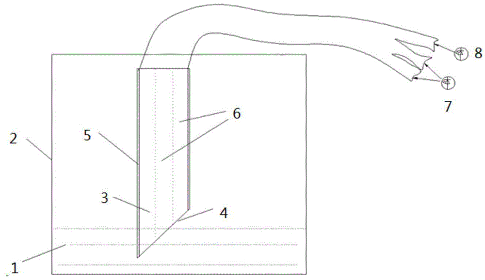
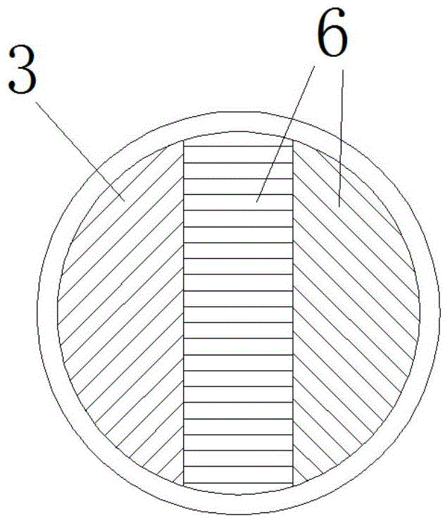
[0021] exist figure 1 Among them, the ends of the transmitting optical fiber bundle 3 and two receiving optical fiber bundles 6 (receiving optical fiber bundles can be 1 or multiple paths, and 2 paths are taken as an example in this embodiment) are combined into a concentrated optical fiber bundle, and their end faces constitute the probe end face 4. The shape structure of the end surface is...


PUM


Abstract

The invention discloses an optical fiber dot mode liquid level sensor, and belongs to photoelectric sensors. The optical fiber dot mode liquid level sensor is used for alarming, indication and the like for the upper limit and the lower limit of the liquid level. The liquid level height is measured mainly through sensitivity of an optical fiber probe to light intensity and different scattering conditions of light of the optical fiber probe in air and liquid. The optical fiber dot mode liquid level sensor is composed of optical fiber bundles and a signal processing circuit. The optical fiber bundles comprise the transmitting optical fiber bundle and the receiving optical fiber bundles. The wedge-shaped end faces of the optical fiber bundles form a detection end face. Sensitivity of liquid level detection can be improved and liquid drop adhesion can be prevented through the wedge-shaped end faces. The signal processing circuit is installed at the other ends of the transmitting optical fiber bundle and the receiving optical fiber bundles, and the structure in which the circuit and the probe are integrated is formed. The sensor and an upper computer are in data communication in communication modes such as RS485 or CAN or the industrial Ethernet. The optical fiber dot mode liquid level sensor is small in size, low in weight, integrated, convenient to install and maintain, light in appearance space, high in sensitivity, simple in signal processing, free of movable accessories and high in reliability.

Description

technical field [0001] The invention belongs to the technical field of photoelectric sensors, and in particular relates to an optical fiber point type liquid level sensor, which is used for alarming and indicating the upper and lower limits of the liquid level. Background technique [0002] With the advancement of aviation technology, real-time and accurate understanding of the liquid level in the fuel tank under flight conditions is of great significance for improving aircraft combat capabilities and safety performance. At present, the sensors used for liquid level measurement have many deficiencies: the hydrostatic liquid level sensor is easily affected by the density of the liquid, and has the problem of low accuracy; the capacitive liquid level sensor must be fixed in the liquid pool during installation, and the installation is completed In order to ensure the accuracy of the measurement, it is necessary to re-calibrate the zero point of the test and maintain it regularl...

Claims


Application Information

Patent Timeline
Patent Type & Authority Applications(China)
IPC IPC(8): G01F23/292
Inventor 葛俊锋闫泽豪叶林华滨龚英桂康
Owner HUAZHONG UNIV OF SCI & TECH
Why Eureka
Try Eureka