
Method for obtaining material thermo-optical coefficient through measuring light spot radius change

A technology of thermo-optic coefficient and spot radius, which is applied in the direction of material analysis, measuring devices, and analyzing materials through optical means, can solve the problems of high price, high cost of measurement, and increased cost of measurement methods, and achieve low measurement cost, Simple and accurate results obtained

Inactive Publication Date: 2015-10-07
SUZHOU UNIV OF SCI & TECH
View PDF1 Cites 4 Cited by
  • Summary
  • Abstract
  • Description
  • Claims
  • Application Information

AI Technical Summary

Problems solved by technology

Z-scan method (Mansoor Sheik-Bahae, Ali A. Said, Tai-Hui Wei, David J. Hagan, E. W. Van Stryland. "Sensitive measurement of optical nonlinearities using a single beam", IEEE J. Quantum Elect, 26, 760- 769 (1990) ) has the characteristics of simple optical path and high sensitivity. It is one of the most commonly used methods to measure the optical nonlinearity of materials, and this method is also often used to study the thermally induced nonlinearity of materials. However, this measurement method requires Using mobile platforms and energy detectors, etc.
In addition, the 4f phase coherent imaging system (G. Boudebs and S. Cherukulappurath, "Nonlinear optical measurements using a 4f coherent imaging system with phase object", Phys. Rev. A, 69, 053813(2004)) needs to compare the acquired images Complicated processing, and relatively high requirements for CCD (Charge-coupled Device, charge-coupled device), which increases the cost of the measurement method
[0003] In summary, most of the previous methods for measuring the thermo-optic coefficient of materials required expensive measurement tools such as energy meters (power meters) and CCDs, and the cost of measurement was high.

Method used


Image

  • Method for obtaining material thermo-optical coefficient through measuring light spot radius change
  • Method for obtaining material thermo-optical coefficient through measuring light spot radius change
  • Method for obtaining material thermo-optical coefficient through measuring light spot radius change

Examples


Embodiment 1

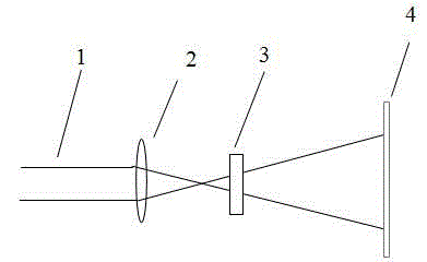
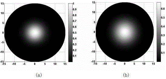
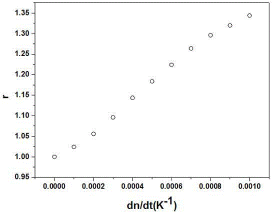
[0019] Embodiment 1: A method for obtaining the thermo-optical coefficient of a material by measuring the change in the radius of the spot, using a continuous Gaussian laser beam as incident light, converging on the sample to be tested by a convex lens, so that the sample to be tested produces a thermal lens effect. The sample to be tested is at a certain distance in front of or behind the focal point of the convex lens in the optical path. After the pulsed laser emitted from the laser is converged by the convex lens, it acts on the sample to be tested near the focal point. After passing the sample, the far-field position of the sample is measured after the sample is measured. Material thermo-optical coefficient, the specific measurement steps are:

[0020] (1) Place the sample to be tested at a position away from the focus of the convex lens, receive the far-field spot and measure the size of the far-field spot;

[0021] (2) Place the sample to be tested at a certain distance near...


PUM


Abstract

The invention discloses a method for obtaining a material thermo-optical coefficient through measuring light spot radius change. A continuous gauss laser beam is used as incident light and is gathered onto a sample to be measured through a convex lens, so that the sample to be measured generates a thermal lens effect; the sample to be detected is positioned in front of or behind a focus point of the convex lens by certain distance in an optical path; pulse laser emitted out from a laser is gathered through the convex lens and acts on the sample to be measured in a position near the focus point; after the pulse laser passes through the sample, the size change of the light spot in a far field position behind the sample is measured to obtain the material thermo-optical coefficient. The method has the advantages that the material thermo-optical coefficient is obtained through measuring the light spot radius change, the material thermo-optical coefficient is simply and accurately obtained under the condition of not requiring measuring tools such as an energy meter and a CCD (charge coupled device), and the measuring cost is low.

Description

Technical field [0001] The invention relates to a method for measuring the optical parameters of a material, in particular to a method for obtaining the thermo-optical coefficient of the material by measuring the change in the radius of the light spot. Background technique [0002] As a basic property of materials, the thermo-optic effect determines the change of refractive index with temperature. This characteristic has a wide range of applications in the field of optoelectronics, such as tunable couplers, filters and sensors. In recent years, the application of thermo-optic effect that has been studied more frequently is thermo-optic effect switch in optical exchange. Compared with mechanical optical switches, thermo-optic effect optical switches have the characteristics of good stability, small size, easy integration, and suitable for mass production. The application of thermo-optic effect requires that the refractive index of the material changes sufficiently with temperatu...

Claims


Application Information

Patent Timeline
IPC IPC(8): G01N21/17
Inventor 沙金巧
Owner SUZHOU UNIV OF SCI & TECH
Learn More