A device for adjusting coherence factor in lithography illumination system

A lighting system and coherence factor technology, applied in the field of lithography, can solve the problems of large zoom ratio of the zoom lens group, affecting the transmittance of the system, increasing the difficulty of design, etc., achieving fast adjustment speed, large adjustment range, and space saving Effect

Active Publication Date: 2017-03-29
INST OF OPTICS & ELECTRONICS - CHINESE ACAD OF SCI
View PDF1 Cites 0 Cited by
  • Summary
  • Abstract
  • Description
  • Claims
  • Application Information

AI Technical Summary

Problems solved by technology

[0006] However, when the lighting system mentioned above wants to obtain a large range of coherence factors, the zoom ratio of the zoom lens group is very large, which makes the design more difficult, and the travel of the moving mirror will be very long when changing from short focus to long focus.
On the other hand, when the laser passes through the glass lens of the lighting system, the energy will be absorbed by the lens, and the zoom lens group and quartz rod will affect the transmittance of the system

Method used


Image

  • A device for adjusting coherence factor in lithography illumination system
  • A device for adjusting coherence factor in lithography illumination system
  • A device for adjusting coherence factor in lithography illumination system

Examples


Embodiment Construction

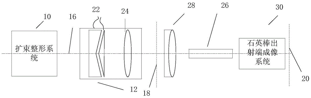
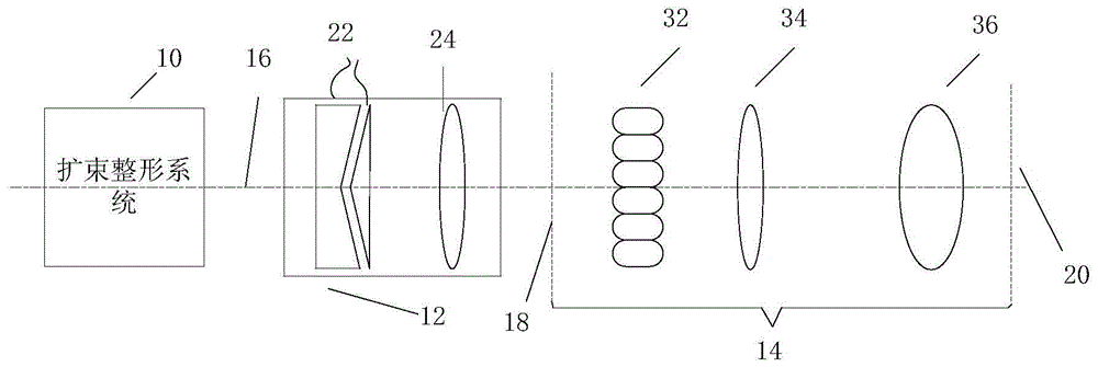
[0036] The specific implementation manner of the present invention will be further described in detail below in conjunction with the accompanying drawings and specific examples.

[0037] The invention can realize multi-level coherence factor conversion with a simple method, improve the transmittance of the lighting system, and improve the exposure efficiency.

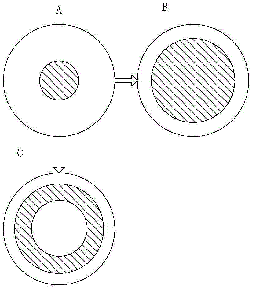
[0038] The present invention first utilizes two groups of reflector groups, and controls each reflector to form the same angle with the optical axis through a rotating motor, and adjusts the numerical aperture of the light beam to adjust the coherence factor of the lighting system. The numerical aperture can be continuously adjusted, that is, the continuous coherence factor. Then use the tapered prism to change the overall height of the light beam, and increase the adjustable range of the coherence factor without adjusting the mirror group. Compared with adjusting the coherence factor of the lighting system only through...


PUM


Abstract

The invention discloses a coherent factor adjusting device in a photoetching illuminating system. The coherent factor adjusting device comprises a reflecting mirror group, a collimating mirror group and a conical prism group, wherein the reflecting mirror group is positioned on an optical path of the front end of the illuminating system, rotates at high precision under the driving of a motor and can have relatively high rotating precision; the collimating mirror group is positioned on an optimal path of the illuminating system behind the reflecting mirror group; the conical prism group is positioned on an emergent light path of the collimating mirror group; uniform light intensity distribution is obtained on a mask surface through rear uniform illuminating subsystems. According to the coherent factor adjusting device, multi-level change of coherent factors is realized by utilizing a simple method, the transmittance rate of the system is increased, and the purposes of simplifying the structure and reducing the cost are achieved.

Description

technical field [0001] The invention relates to the field of photolithography, in particular to a coherence factor adjustment module in a photolithography illumination system. Background technique [0002] Optical projection lithography is an optical exposure process that uses the principle of optical projection imaging to transfer the integrated circuit (IC) pattern on the reticle to the rubber-coated silicon wafer in a step-by-step or step-and-scan manner. . [0003] According to different exposure requirements when the lithography machine is actually working, different numerical apertures or coherence factors are required on the silicon wafer. [0004] The existing technology is mainly to adjust the coherence factor of the lighting system by combining the zoom lens group with the conical prism. [0005] For example, US Pat. No. 6,452,662 adopts the method of adjusting the coherence factor of the illumination system by combining a zoom lens group with a tapered prism. F...

Claims


Application Information

Patent Timeline
Patent Type & Authority Patents(China)
IPC IPC(8): G03F7/20G02B26/08
Inventor 卢亮张海波林妩媚
Owner INST OF OPTICS & ELECTRONICS - CHINESE ACAD OF SCI
Why Eureka
Try Eureka