A Scanning Imaging System for Weak Light Signals

A scanning imaging and line scanning technology, which is applied in the field of scanning imaging systems with weak light signals, can solve the problems of weak signals and low imaging speed, and achieve the effects of fast imaging speed, good imaging effect and improving light energy utilization rate.

Inactive Publication Date: 2016-05-04
WUHAN OE BIO CO LTD
View PDF6 Cites 0 Cited by
  • Summary
  • Abstract
  • Description
  • Claims
  • Application Information

AI Technical Summary

Problems solved by technology

[0005] In view of the above defects or improvement needs of the prior art, the present invention provides a high-speed low-light scanning imaging system, the purpose of which is to combine a specific line scanning module and a spot shaping module, so that the imaging of the illumination area and the line detector The area is matched to improve the lighting efficiency, thereby solving the technical problems of weak signal and low imaging speed when using line detectors for imaging

Method used


Image

  • A Scanning Imaging System for Weak Light Signals
  • A Scanning Imaging System for Weak Light Signals
  • A Scanning Imaging System for Weak Light Signals

Examples


Embodiment 1

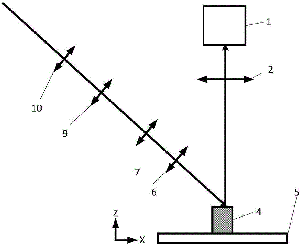
[0033] An imaging system such as figure 1 Shown is the setup for high-speed scanning imaging using infrared light. Including line scan module and spot shaping module.

[0034] The line scan module includes a line detector 1 (TDI-CCD) and an imaging lens 2, and the photosensitive surface of the TDI-CCD is mapped to an area on the focal plane by the imaging lens 2 such as Figure 4 As shown, it is a rectangle whose length is B and width is C. We need to shape the illumination spot to form an elliptical illumination area 12 that can just cover the imaging area 13, so that we can maximize the energy of the illumination light.

[0035] The spot shaping module sequentially includes a beam expanding unit and a beam reducing unit according to the direction of the optical path. The beam expander unit includes a first spherical mirror concave lens 10 and a second spherical mirror convex lens 9 in the optical path, the optical axes of which are coincident and confocal. The beam shrin...

Embodiment 2

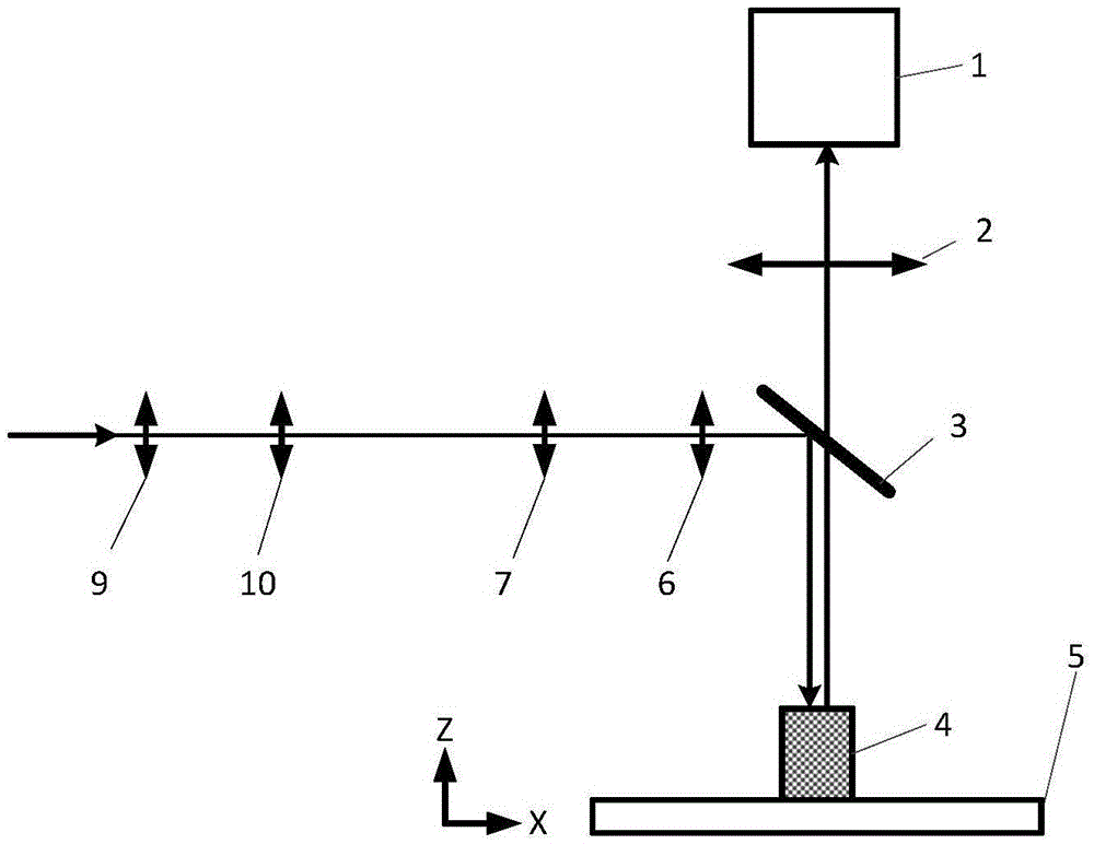
[0037]An imaging system such as figure 2 As shown, the high-speed scanning imaging device for laser-excited fluorescence includes a line scanning module and a spot shaping module.

[0038] The line scan module includes a line detector 1 (TDI-CCD) and an imaging lens 2, and the photosensitive surface of the TDI-CCD is mapped to an area on the focal plane by the imaging lens 2 such as Figure 4 As shown, it is a rectangle whose length is B and width is C. We need to shape the illumination spot to form an elliptical illumination area 12 that can just cover the imaging area 13, so that we can maximize the energy of the illumination light.

[0039] The spot shaping module sequentially includes a beam expanding unit and a beam reducing unit according to the direction of the optical path. The beam expander unit includes a first spherical mirror-convex lens 10 and a second spherical mirror-convex lens 9 in the optical path, the optical axes of which are coincident and confocal. Th...

Embodiment 3

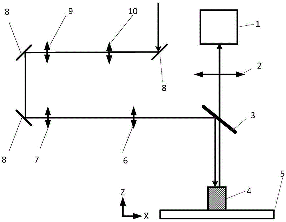
[0042] An imaging system such as image 3 Shown is a device for high-speed scanning imaging using laser-excited fluorescence, including a line scanning module and a spot shaping module.

[0043] The line scan module includes a line detector 1 (TDI-CCD) and an imaging lens 2, and the photosensitive surface of the TDI-CCD is mapped to an area on the focal plane by the imaging lens 2 such as Figure 4 As shown, it is a rectangle whose length is B and width is C. We need to shape the illumination spot to form an elliptical illumination area 12 that can just cover the imaging area 13, so that we can maximize the energy of the illumination light.

[0044] The spot shaping module sequentially includes a beam expanding unit and a beam reducing unit according to the direction of the optical path. The beam expander unit includes a first spherical mirror-convex lens 10 and a second spherical mirror-convex lens 9 in the optical path, the optical axes of which coincide and are confocal. ...


PUM


Abstract

The invention discloses a scanning imaging system for weak light signals. The imaging system comprises a line scanning module and a light spot shaping module. The line scanning module comprises a line detector and an imaging lens. The light spot shaping module successively comprises a beam expanding unit and a beam compressing unit according to an optical path direction; a collimation light beam forms elliptical light spots through the light spot shaping module for illuminating a sample; and the sample generates light signals, the light signals, after being focused by an imaging lens of the line scanning module, are acquired by the line detector of the line scanning module for imaging, the sample and the line detector 1 move relative to each other for scanning, the scanning direction of the line detector is vertical to the long axes of the elliptical light spots, the long axes of the elliptical light spots are greater than the length of an imaging area of the line detector, and the ratio of the short axes of the elliptical light spots to the width of the imaging area of the line detector ranges from 0.8 to 1.5. The scanning imaging system for the weak light signals improves the illumination efficiency and solves the technical problems of quite weak signals and not high imaging speed during imaging of the line detector.

Description

technical field [0001] The invention belongs to the field of weak signal imaging, and more specifically relates to a scanning imaging system for weak light signals. Background technique [0002] Weak signal imaging is a frequently encountered imaging problem. Imaging weaker signals requires longer exposure times, limiting imaging speed. If high-speed imaging is performed on a signal with strong intensity, the collected signal will be relatively weak because the exposure time is very short. In industrial and other application fields, high-speed and low-light scanning imaging have a very wide demand, and higher imaging speed means higher product inspection efficiency. In the field of scientific research, especially in situations where high temporal resolution imaging is required or a large number of sample images need to be obtained, high-speed scanning imaging is necessary. [0003] Scanning imaging is a very important high-speed imaging method, including point scanning im...

Claims


Application Information

Patent Timeline
Patent Type & Authority Patents(China)
IPC IPC(8): H04N1/04H04N1/024
Inventor 骆清铭龚辉曾绍群杨涛尚振华
Owner WUHAN OE BIO CO LTD
Why Eureka
Try Eureka