
Coupling type inertial cyclone fluid particle heterogeneous separation device and method

A technology of separation device and cyclone separator, which is applied in the direction of the cyclone device and the device in which the axial direction of the cyclone can be reversed, etc., which can solve the problems of long separation distance and time, large penetration of solid phase particles, etc. Achieve the effect of reducing design and manufacturing difficulty, reducing research and development time and costs, and improving processing flow

Inactive Publication Date: 2015-10-14
UNIV OF SHANGHAI FOR SCI & TECH
View PDF7 Cites 10 Cited by
  • Summary
  • Abstract
  • Description
  • Claims
  • Application Information

AI Technical Summary

Problems solved by technology

[0003] The purpose of the present invention is to solve the problem that the same particle concentration at each position on the inlet airflow section of the cyclone separator leads to large penetration of solid particles, long separation distance and time, and proposes a coupled inertial cyclone fluid particle non-uniform The phase separation device and method, that is, the method of organically coupling the inertial bend and the volute type cyclone separator, realizes the improvement of the single separation efficiency of the existing separation device, and improves the overall efficiency of the multi-stage separation system in series

Method used


Image

  • Coupling type inertial cyclone fluid particle heterogeneous separation device and method
  • Coupling type inertial cyclone fluid particle heterogeneous separation device and method
  • Coupling type inertial cyclone fluid particle heterogeneous separation device and method

Examples


Embodiment Construction

[0025] The present invention will be further described below in conjunction with specific implementation examples.

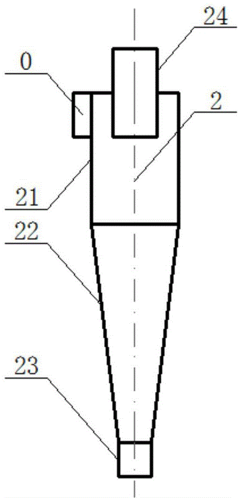
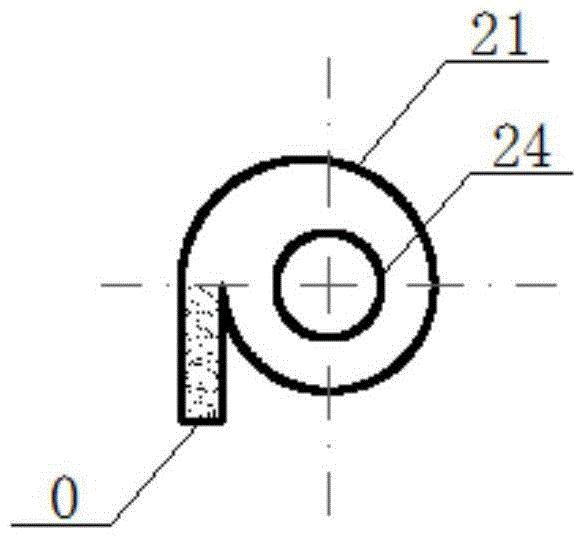
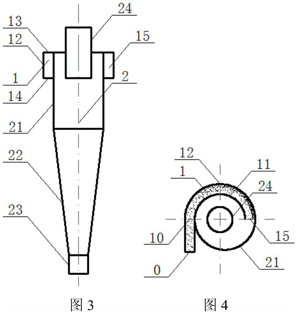
[0026] Such as image 3 , as shown in 4, a coupled inertial cyclone fluid particle heterogeneous phase separation device, including an inertial bend 1 and an integrated volute tangential inlet cyclone separator 2 coupled with it and its connected components Barrel 21 , cone 22 , particle outlet 23 and fluid outlet 24 .

[0027] The inertia bend 1 adopts a one-way connection mode, and its inlet 10 is connected to the external pipeline 0, and its outlet 15 is connected to the inlet port 20 of the volute of the cyclone separator. The inertia curve 1 is composed of the concentric fan-shaped annular space enclosed by the inner arc plate 11, the outer arc plate 12, the upper top plate 13 and the lower bottom plate 15, wherein the inner arc plate 11 is the cylinder 21 of the cyclone separator. Project the coincidence structure for the space. The connection can be we...


PUM


Abstract

The invention relates to a coupling type inertial cyclone fluid particle heterogeneous separation device and method. The device comprises an inertial curve and a cyclone separator coupled with the inertial curve and provided with an integrated volute tangential inlet. The inertial curve and the cyclone separator are integrally coupled, the fluid phase and the particle phase firstly enter an inertial curve body through an external pipeline, the differential particle concentration gradient is generated, the fluid phase and the particle phase enter the cyclone separator integrally coupled with the inertial curve to be separated, and therefore the defects existing in the separation process under the particle concentration uniformity or concentration-gradient-free condition in the traditional separation process are overcome. The inertial curve is organically integrated into fluid-particle radial concentration space, the concentration gradient with the outer portion higher than the inner portion is generated under the effect of a centrifugal field, the particle penetration amount caused by short-circuit current entrainment after particles enter the cyclone separator can be reduced, the distance or time of the particles moving towards the capture wall is shortened, and the heterogeneous separation efficiency is effectively improved under the condition that the pressure drop of the separator is not obviously increased.

Description

technical field [0001] The invention relates to a fluid particle heterogeneous two-phase (gas-solid or gas-liquid) separation and purification technology, in particular to a coupled inertial swirling fluid particle heterogeneous phase separation method and its device. Background technique [0002] Cyclone heterogeneous separation equipment (that is, cyclone separator, including cyclone separator and hydrocyclone, etc.) has the advantages of simple structure, low cost and easy maintenance, and is suitable for harsh operating environments such as high temperature, high pressure, and high corrosion , Widely used in the separation and purification of gas particles in the fields of energy, chemical industry, materials and environment. When the non-uniform two-phase flow (dilute phase or dense phase) of fluid particles enters the inner space of the cyclone separator, the spiral movement flows downward into the lower part of the separator, and reverses upward after reaching the nat...

Claims


Application Information

Patent Timeline
IPC IPC(8): B04C7/00B04C5/04
Inventor 赵兵涛
Owner UNIV OF SHANGHAI FOR SCI & TECH
Learn More