Alignment assembly and method for aligning rotating shaft of rotating table type laser direct writing device to direct writing optical axis

A technology of laser direct writing and rotary table, applied in laser welding equipment, welding equipment, metal processing equipment, etc., can solve problems such as limited applicability, difficulty in writing wedge-shaped reflective substrates, and great influence of surface shape on detection accuracy

Active Publication Date: 2015-10-14
JILIN UNIV
View PDF3 Cites 17 Cited by
  • Summary
  • Abstract
  • Description
  • Claims
  • Application Information

AI Technical Summary

Problems solved by technology

If there is an alignment error, errors will be introduced into parameters such as the scanning radius of the micro-relief structure during the processing of the optical element, which will eventually have a great impact on the quality of the optical element
[0003] At present, there are mainly the following technologies to solve the alignment between the rotating shaft of the laser direct writing machine and the direct writing optical axis: Rotate the grating ruler, observe the movement of the grating stripes through the imaging system or use the CCD to monitor the light and dark changes of the laser spot reflected by the grating to judge the two axes Whether it is aligned or not, the disadvantage is that the alignment accuracy is difficult to improve due to the influence of the grating period, and the operation is more complicated; using a photoelectric scanning microscope to align the two axes, even if the error can be less than 0.1μm, the operation is complicated and the cost is high; the use of monitoring rotation The laser reflected by the 10-degree wedge is aligned to the two axes. The disadvantage is that the detection accuracy is greatly affected by the surface of the wedge, and it is very difficult to make a high-precision wedge-shaped reflective substrate.
[0004] The above methods can align the shafts based on air bearings with at least sub-micron precision, but it is difficult to visually evaluate the alignment during the alignment process, and the operation is complicated; The runout in the radial direction and the radial direction is relatively large, and it is difficult to judge the alignment situation by using the above method, resulting in limited applicability of the above method

Method used


Image

  • Alignment assembly and method for aligning rotating shaft of rotating table type laser direct writing device to direct writing optical axis

Examples


Embodiment Construction

[0029] The technical solutions of the present invention will be further specifically described below through the embodiments and in conjunction with the accompanying drawings. In the specification, the same or similar reference numerals designate the same or similar bottom members. The following description of the embodiments of the present invention with reference to the accompanying drawings is intended to explain the general inventive concept of the present invention, but should not be construed as a limitation of the present invention.

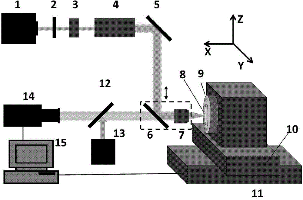
[0030] figure 1 It is a structural schematic diagram of the alignment assembly of the rotation axis of the rotary table laser direct writing device and the direct writing optical axis according to an exemplary embodiment of the present invention, wherein: 1 is a laser, 2 is a linear gradient neutral density filter, 3 is an optical gate, 4 is a beam expander, 5 is a first dielectric mirror, 6 is a second dielectric mirror, 7 is an objectiv...


PUM

PropertyMeasurementUnit
diameteraaaaaaaaaa
thicknessaaaaaaaaaa

Abstract

Disclosed is an assembly for aligning a rotating shaft of a rotating table type laser direct writing device to the direct writing optical axis. The direct writing device comprises a laser source, a laser path and a rotating table, wherein a laser modulator, a first reflector, a second reflector and a microscope objective are sequentially arranged on the laser path, laser beams are modulated by the laser modulator and then reflected by the first and second reflectors to be incident onto the microscope objective, and the tabletop of the rotating table is perpendicular to the direct writing optical axis. The alignment assembly comprises a panel piece and a digital imaging system, wherein a metal film is arranged on one side of the panel piece, the panel piece is fixed to the tabletop of the rotating table, the metal film faces the microscope objective, and the digital imaging system comprises a lighting source, a visible light splitter, an image sensor and a displayer. Visible light from the lighting source is reflected by the light splitting piece and then passes through the second reflector to be incident onto the metal film through the microscope objective, visible light reflected by the metal film passes through the microscope objective, the second reflector and the visible light splitter to enter the image sensor, and the displayer displays images from the image sensor.

Description

technical field [0001] Embodiments of the present invention belong to the field of laser micro-nano processing, and in particular, relate to an alignment component and method for aligning a rotation axis of a rotary table laser direct writing device with a direct writing optical axis. technical background [0002] Laser micro-nano direct writing technology is a digital processing technology, which has the advantages of high processing precision, complex shape and wide range of processing materials. The rotary table laser direct writing technology under the cylindrical coordinate system has the advantages of high processing efficiency, large processing range and high processing precision compared with scanning galvanometer processing and sample table piezoelectric or linear motor raster scanning processing. It is suitable for the processing of centrosymmetric micro-nano structures and has become an important technical means for making diffractive micro-optical elements. Rota...

Claims


Application Information

Patent Timeline
Patent Type & Authority Applications(China)
IPC IPC(8): B23K26/70
Inventor 孙洪波于颜豪陈岐岱姜俊
Owner JILIN UNIV
Why Eureka
Try Eureka