Lifting adjusting device for pressure container

The technology of a pressure vessel and a lifting pipe is applied in the field of pressure vessel lifting and debugging devices, which can solve the problems of inconvenient vertical lifting movement of the pressure vessel, and achieve the effect of convenient vertical lifting control.

Inactive Publication Date: 2015-10-14
ZHANGJIAGANG SHUNJIA INSULATION TECH
View PDF6 Cites 0 Cited by
  • Summary
  • Abstract
  • Description
  • Claims
  • Application Information

AI Technical Summary

Problems solved by technology

The existing pressure vessel is inconvenient to realize vertical lifting movement

Method used


Image

  • Lifting adjusting device for pressure container

Examples


Embodiment Construction

[0012] In order to make the technical means, creative features, goals and effects achieved by the present invention easy to understand, the present invention will be further described below in conjunction with specific embodiments.

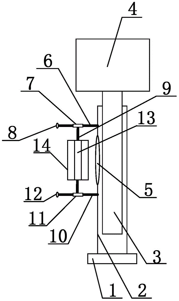
[0013] Such as figure 1 As shown, a lifting and debugging device for a pressure vessel includes a base 1. A guide tube 2 is provided on the base 1. The guide tube 2 is a tubular structure. The guide tube 2 is arranged vertically. The pipe 3 is vertically arranged, the end of the lifting pipe 3 is provided with a pressure vessel 4, the side wall of the guide pipe 2 is provided with a slot 5, the side wall of the guide pipe 2 is provided with a first guide rod 6, and the first guide rod 6 Arranged horizontally, the first guide rod 6 is arranged above the slot 5, the first guide rod 6 is sleeved with the first slider 7, the side wall of the guide tube 2 is provided with a second guide rod 10, and the second guide rod 10 is Arranged horizontally, the...


PUM


Abstract

The invention discloses a lifting adjusting device for a pressure container. The lifting adjusting device comprises a base, a guiding tube is arranged on the base, a lifting tube is sleeved with the guiding tube, the pressure container is arranged at the end of the lifting tube, an open groove is formed in the side wall of the guiding tube, guiding rods are arranged on the side wall of the guiding tube and sleeved with sliding blocks, a connecting rod is arranged between the sliding blocks and sleeved with a rotating tube, and the lifting tube and the rotating tube are connected through threads in a meshed mode. Rotation of the rotating tube can control the lifting tube to vertically move along the guiding tube in a lifting mode, so that vertical lifting control over the pressure container is convenient.

Description

technical field [0001] The invention relates to a lifting and debugging device, in particular to a pressure vessel lifting and debugging device. Background technique [0002] The manufacturing process of pressure vessels can generally be divided into: raw material acceptance process, scribing process, cutting process, rust removal process, machining (including planing, etc.) process, rolling process, assembly process, welding process (product welding test plate) , Non-destructive testing process, drilling and scribing process, general inspection process, heat treatment process, pressure test process, anti-corrosion process. Different welding methods have different welding processes. The welding process is mainly determined according to the material, grade, chemical composition of the workpiece to be welded, the structure type of the weldment, and the welding performance requirements. First of all, it is necessary to determine the welding method, such as manual arc welding,...

Claims


Application Information

Patent Timeline
Patent Type & Authority Applications(China)
IPC IPC(8): B23K37/00
CPCB23K37/00B23K2101/12
Inventor 邬少忠
Owner ZHANGJIAGANG SHUNJIA INSULATION TECH
Why Eureka
Try Eureka