Single beam splitter transmission-type pohotonic crystal fiber resonant cavity

一种光子晶体光纤、透射式的技术,应用在光的干涉和光学传感领域,能够解决腔内损耗大、不利高清晰度、谐振腔调节难度大等问题,达到腔内总损耗降低、提高清晰度、降低调节难度的效果

Active Publication Date: 2015-10-14
BEIHANG UNIV
View PDF7 Cites 5 Cited by
  • Summary
  • Abstract
  • Description
  • Claims
  • Application Information

AI Technical Summary

Problems solved by technology

The existing transmission resonator is composed of two optical beam splitters, four fiber collimators and four photonic crystal fiber collimators. Due to the large number of components, it is difficult to adjust the resonator and the loss in the cavity is large, which is not conducive to achieve high definition
In addition, because there are two independent photonic crystal fibers in the resonant cavity of this structure, it is more difficult to wind a photonic crystal fiber ring than to wind only one photonic crystal fiber

Method used


Image

  • Single beam splitter transmission-type pohotonic crystal fiber resonant cavity

Examples


Embodiment Construction

[0018] The technical solutions in the embodiments of the present invention will be clearly and completely described below in conjunction with the accompanying drawings in the embodiments of the present invention. Obviously, the described embodiments are only some of the embodiments of the present invention, not all of them. Based on the embodiments of the present invention, all other embodiments obtained by persons of ordinary skill in the art without making creative efforts belong to the protection scope of the present invention.

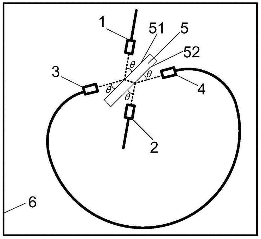
[0019] The invention is a single beam splitter transmission photonic crystal fiber resonator, such as figure 1 As shown, it includes a first fiber collimator 1, a second fiber collimator 2, a first photonic crystal fiber collimator 3, a second photonic crystal fiber collimator 4, an optical beam splitter 5, and a fixing device 6;

[0020] The first optical fiber collimator 1, the second optical fiber collimator 2, the first photonic crystal fiber c...


PUM


Abstract

The present invention relates to a single beam splitter transmission-type pohotonic crystal fiber resonant cavity, which comprises a first fiber collimator, a second fiber collimator, a first pohotonic crystal fiber collimator, a second pohotonic crystal fiber collimator, an optical beam splitter, and a fixed device. The first fiber collimator, the second fiber collimator, the first pohotonic crystal fiber collimator, the second pohotonic crystal fiber collimator, and the optical beam splitter are fixed on the fixed device. Pigtails of the first fiber collimator and the second fiber collimator are an input port or an output port seperately; the first pohotonic crystal fiber collimator is connected with the pigtail of the second pohotonic crystal fiber collimator.Only one optical beam splitter and two pohotonic crystal fiber collimator are used to structure a resonant cavity, and the number of devices in the resonant cavity is reduced by half, so that the inner structure of the resonant cavity is simple, the difficulty of the resonant cavity regulation is decreased, and the volume of the resonant cavity is reduced.

Description

technical field [0001] The invention relates to a single-beam splitter transmission photonic crystal fiber resonator cavity, which belongs to the technical field of light interference and optical sensing. Background technique [0002] Optical resonators are research hotspots in the fields of lasers, optical sensing, and inertia. One of the key indicators is clarity or quality factor, which often determines the performance of the entire system. In the resonant optical gyroscope, the definition of the passive resonant cavity determines the limit sensitivity of the gyro, and the non-reciprocal error of the transmissive resonant cavity is smaller than that of the reflective resonant cavity. Therefore, the high-definition transmissive resonant cavity is developed The key to high-precision resonant optical gyroscope. [0003] Photonic crystal fibers have many excellent properties, but they are quite different from traditional optical fibers. Developing high-performance photonic c...

Claims


Application Information

Patent Timeline
Patent Type & Authority Applications(China)
IPC IPC(8): G02B6/28G02B6/32
CPCG02B6/2821G02B6/32G02B6/032G01C19/727G02B6/2934G01C19/72G02B6/262G02B27/30
Inventor 冯丽爽王俊杰郅银周焦洪臣王琪伟宋文帅
Owner BEIHANG UNIV
Why Eureka
Try Eureka