Oxygen reduction catalyst, oxygen reduction electrode, and fuel cell
A fuel cell and catalyst technology, applied in solid electrolyte fuel cells, fuel cells, physical/chemical process catalysts, etc., can solve the problems that platinum fuel cells are not fully popularized and the manufacturing cost is high
- Summary
- Abstract
- Description
- Claims
- Application Information
AI Technical Summary
Problems solved by technology
Method used
Image

Examples
no. 1 approach
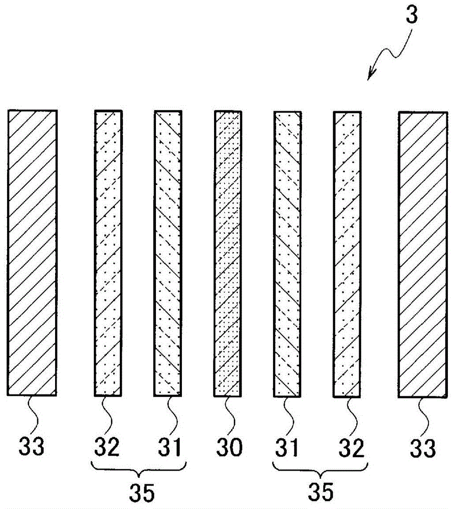
[0032] The oxygen reduction catalyst according to the first embodiment is a nitrogen-doped carbon nanowall or a nitrogen-doped carbon nanowall sheet. Furthermore, the oxygen reduction electrode according to the first embodiment includes a gas diffusion layer and an oxygen reduction catalyst as a catalyst layer. Furthermore, the fuel cell according to the first embodiment includes an electrolyte membrane, a gas diffusion layer, an oxygen reduction catalyst as a catalyst layer, and a separator.
[0033] (oxygen reduction catalyst)
[0034] The oxygen reduction catalyst according to the first embodiment is a carbon nanowall sheet composed of nitrogen-doped carbon nanowall or one or more nanographites smaller than the carbon nanowall. The carbon nanowall sheet is obtained by pulverizing carbon nanowalls doped with nitrogen. The carbon nanowall doped with nitrogen is, for example, grown on a substrate such as a silicon substrate and doped with nitrogen, and then peeled off from t...
Embodiment 1
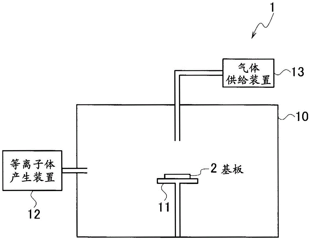
[0052] exist Figure 4 The SEM image of the carbon nanowall related to Example 1 is shown in . The carbon nanowall doped with nitrogen, using figure 1 The device 1 presented here is obtained by doping nitrogen into the carbon nanowalls on the silicon substrate under the condition B2 after the carbon nanowalls are formed on the silicon substrate under the condition B1.
[0053] Condition B1: pressure 0.67Pa, heating temperature 600°C, discharge current 50A, flow rate of argon 80 sccm, flow rate of hydrogen 10 sccm, flow rate of methane 10 sccm, growth time 360 minutes
[0054] Condition B2: pressure 0.67Pa, heating temperature 700°C, discharge current 70A, flow rate of argon 80 sccm, flow rate of hydrogen 0 sccm, flow rate of nitrogen 20 sccm, treatment time 1 minute
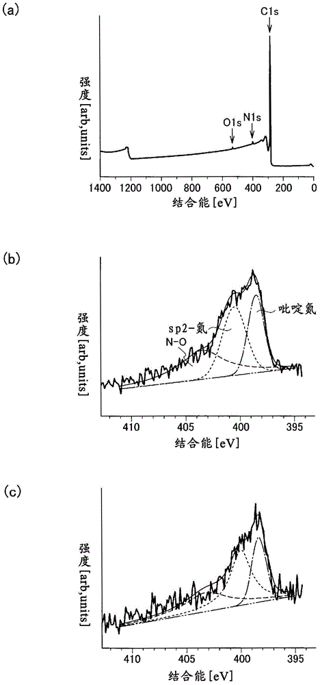
[0055] exist Figure 5 (a) shows the Raman scattering spectrum of the nitrogen-doped carbon nanowall of Example 1. exist Figure 5 (b) shows the XPS spectrum of the carbon nanowall of Example 1. exist F...
Embodiment 2
[0060] The nitrogen-doped carbon nanowall of embodiment 2 utilizes as above figure 1 The device 1 presented here is obtained by doping nitrogen into the carbon nanowalls on the silicon substrate under the condition C2 after the carbon nanowalls are formed on the silicon substrate under the condition C1.
[0061] Condition C1: pressure 0.67Pa, heating temperature 800°C, discharge current 50A, flow rate of argon 80 sccm, flow rate of hydrogen 0 sccm, flow rate of methane 20 sccm, growth time 360 minutes
[0062] Condition C2: pressure 0.67Pa, heating temperature 800°C, discharge current 50A, flow rate of argon 80 sccm, flow rate of hydrogen 10 sccm, flow rate of nitrogen 10 sccm, treatment time 1 minute
[0063] exist Figure 6 (a) shows the Raman scattering spectrum of the nitrogen-doped carbon nanowall of Example 2. exist Figure 6 (b) shows the XPS spectrum of the carbon nanowall of Example 2. exist Figure 6 (c) shows the Raman scattering spectrum of the carbon nanowa...
PUM
| Property | Measurement | Unit |
|---|---|---|
| thickness | aaaaa | aaaaa |
| crystallinity | aaaaa | aaaaa |
Abstract
Description
Claims
Application Information