Bilateral laser-InFocus electric arc composite welding method for T-type joint

An -infocus and hybrid welding technology, applied in the field of laser-InFocus arc hybrid welding on both sides of T-shaped joints, can solve the problems of high laser power requirements, high cost, and small arc penetration, and achieve high current force and energy density , Welding speed is fast, and the effect of reducing positioning variables

Inactive Publication Date: 2015-10-21
HARBIN INST OF TECH
View PDF6 Cites 7 Cited by
  • Summary
  • Abstract
  • Description
  • Claims
  • Application Information

AI Technical Summary

Problems solved by technology

[0005] The present invention aims at the problems existing in the laser-arc composite synchronous welding of T-joints of medium and thick plates, the arc penetration is small, the laser power requirements are large, and the cost is high, and a double-sided laser-InFocus arc hybrid welding of T-joints is proposed. method

Method used


Image

  • Bilateral laser-InFocus electric arc composite welding method for T-type joint
  • Bilateral laser-InFocus electric arc composite welding method for T-type joint
  • Bilateral laser-InFocus electric arc composite welding method for T-type joint

Examples


specific Embodiment approach 1

[0023] Specific embodiment one: A kind of T-joint bilateral laser-InFocus electric arc hybrid welding method of this embodiment, it is carried out according to the following steps:

[0024] Step 1: Process the part of the workpiece to be welded into a groove or not. Before welding, grind the double-sided symmetrical welding groove and the surface within 30mm of the two sides, and then clean the groove and both sides of the groove with acetone. side surface;

[0025] Step 2: the workpiece is fixed on the fixture to be welded;

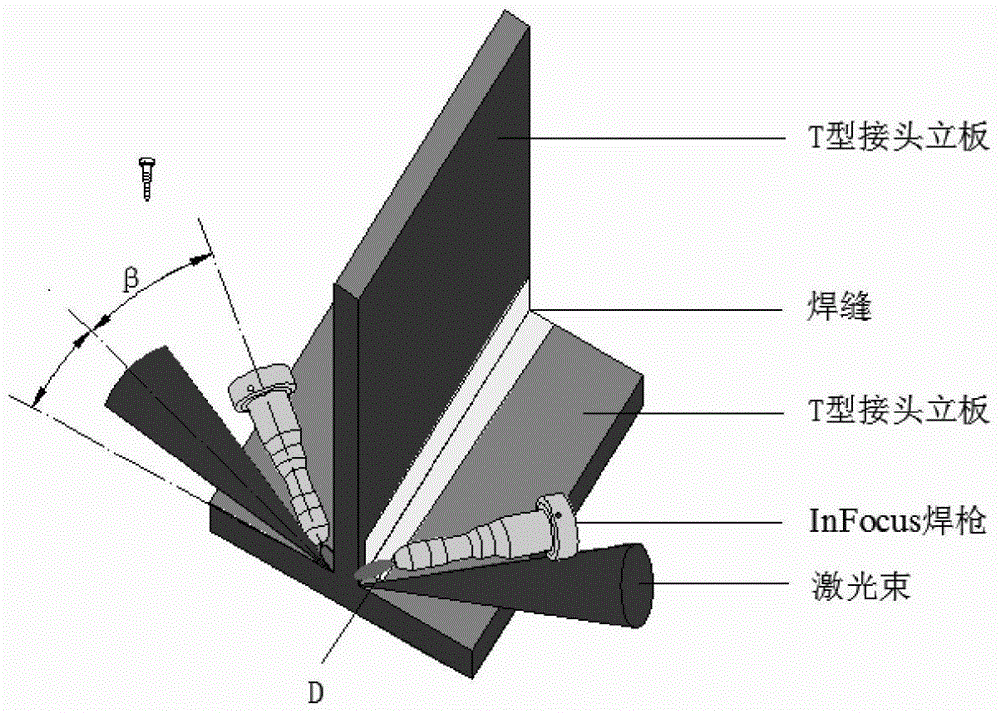
[0026] Step 3: Keep the angle between the laser beam and the arc and the longitudinal surface of the T-joint panel as α, α is 10°-45°, and the angle β between the laser beam and the arc is 30°-45°, adjust The distance between the cathode end point and the laser focal plane is 2-3mm, and the distance between the two heat sources is 1-2mm;

[0027] Step 4: Set the process parameters, the laser power on both sides is 1000W~3000W; the arc current on both s...

specific Embodiment approach 2

[0030] Embodiment 2: The difference between this embodiment and Embodiment 1 is that the laser beam is perpendicular to the normal direction of the transverse surface of the T-joint panel, and the welding is carried out along the normal direction of the transverse surface of the T-joint panel. Others are the same as in the first embodiment.

specific Embodiment approach 3

[0031] Specific embodiment three: the difference between this embodiment and specific embodiment one is that the double-sided laser-InFocus arc hybrid welding method of the T-shaped joint refers to using two laser beams and two InFocus welding torches on both sides of the T-shaped joint respectively on both sides of the joint. Side forming method of laser-InFocus composite and simultaneous welding. Others are the same as in the first embodiment.


PUM

PropertyMeasurementUnit
thicknessaaaaaaaaaa
thicknessaaaaaaaaaa
thicknessaaaaaaaaaa

Abstract

The invention discloses a bilateral laser-InFocus electric arc composite welding method for a T-type joint, and relates to a welding method. The method comprises: I, processing a to-be-welded part and fixing the to-be-welded part by a clamp; II, keeping an included angle alpha between an InFocus welding gun and a panel longitudinal surface of the T-type joint at 30 degrees to 45 degrees, and keeping an included angle beta between the InFocus welding gun and a T-type bottom plate at 30 degrees; III, setting bilateral laser power to 1000W-3000W, setting bilateral electric-arc current to 200A-900A, setting gas flow of an electric-arc welding gun to 15L / min to 30L / min, and setting welding speed to 1.0m / min to 5.0m / min; and IV, implementing welding. Compared with the peak value of conventional ITG electric arc 400A, current acting force and energy density are relatively large, key hole welding can be realized, depth of fusion is large, welding speed is high, and welding efficiency is improved; during welding of a medium-thickness plate, laser power is reduced by increasing welding current, so that the welding cost is reduced.

Description

technical field [0001] The invention relates to a double-sided laser-InFocus arc composite welding method of a T-shaped joint, which belongs to the field of material processing engineering. Background technique [0002] T-shaped structures are widely used in industries such as ships, aerospace and vehicles. With the development of ships, aerospace and vehicles to large tonnage and large carrying capacity, the demand for thick T-shaped structures is increasing. Therefore, increasing the thickness The welding efficiency and welding quality of the plate T-joint are of great significance. At present, for T-joints, the widely used welding process is to weld the weld seam on one side first, then use carbon arc gouging to do the root cleaning work or plan out the groove on the other side, and then weld the other side of the weld seam. Its disadvantages are low welding efficiency, long welding cycle, and large welding deformation. After the first weld is welded by one-sided sequent...

Claims


Application Information

Patent Timeline
Patent Type & Authority Applications(China)
IPC IPC(8): B23K26/348
CPCB23K26/00B23K28/02
Inventor 杨雨禾雷正龙陈彦宾陈曦李鹏张可召
Owner HARBIN INST OF TECH
Why Eureka
Try Eureka