Automatic chamfering, cutting-off and deburring device for steel pipe

A deburring and automatic technology, applied in the field of machining, can solve the problems of increased tool production and purchase costs, increased production costs of enterprises, and increased chamfering processes, and achieves the effect of simple structure, reduced production costs of enterprises, and improved machining accuracy.

Inactive Publication Date: 2015-10-21
GUIZHUO SHUNAN ELECTROMECHANICAL EQUIP CO LTD
View PDF7 Cites 3 Cited by
  • Summary
  • Abstract
  • Description
  • Claims
  • Application Information

AI Technical Summary

Problems solved by technology

Although the existing equipment can already meet the blanking requirements for pipe materials such as rollers, for steel pipes with high processing precision requirements, it is generally necessary to chamfer the inner corners, that is, to remove burrs, and the existing equipment cannot meet the high precision requirements. In particular, it is not possible to chamfer the inner wall of the end of the tube to achieve the ability to automatically remove all burrs. For example, the barrel of the barrel feeder requires that the inner and outer walls mu

Method used


Image

  • Automatic chamfering, cutting-off and deburring device for steel pipe
  • Automatic chamfering, cutting-off and deburring device for steel pipe
  • Automatic chamfering, cutting-off and deburring device for steel pipe

Examples


Embodiment Construction

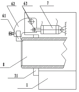
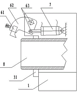
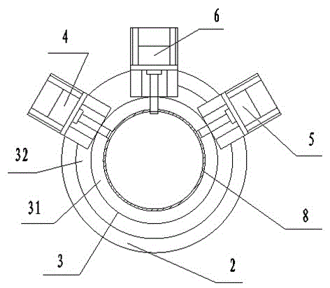
[0014] Such as figure 1 , figure 2 and image 3 As shown, a steel pipe automatic chamfering, cutting and deburring device of the present invention includes a machine tool 1, a support 2, a positioning mechanism 3, an outer corner chamfering mechanism 4, a cutting mechanism 5, an inner corner chamfering mechanism 6, and a hydraulic cylinder 7. The seat 2 is arranged on the machine tool 1, the positioning mechanism 3 includes a clamp 31 and an auxiliary clamp 32, the chamfering mechanism 4, the cutting mechanism 5 and the chamfering mechanism 6 are respectively arranged on the support 2, and the chamfering mechanism 6 It includes a tool 61, a tool holder 62 and a hinge shaft 63, the tool 61 is arranged on the tool holder 62, the tool holder 62 is respectively connected to the axial main shaft and the radial main shaft of the hydraulic cylinder 7 through the hinge shaft 63, and also includes An automatic control system, the automatic control system is electrically connected wi...


PUM


Abstract

The invention relates to an automatic chamfering, cutting-off and deburring device for a steel pipe. The device comprises a machine tool, a bracket, a positioning mechanism, an outer corner chamfering mechanism, a cutting-off mechanism, an inner corner chamfering mechanism and a hydraulic cylinder, wherein the bracket is arranged on the machine tool; the positioning mechanism comprises a clamp and an auxiliary clamp; the outer corner chamfering mechanism, the cutting-off mechanism and the inner corner chamfering mechanism are arranged on the bracket; the inner corner chamfering mechanism comprises a cutter, a cutter rest and hinged shafts; the cutter is arranged on the cutter rest; the cutter rest is connected with an axial spindle and a radial spindle of the hydraulic cylinder through the hinged shafts respectively. The automatic chamfering, cutting-off and deburring device further comprises an automatic control system, and the automatic control system is electrically connected with the outer corner chamfering mechanism, the cutting-off mechanism and the inner corner chamfering mechanism. By the adoption of the automatic chamfering, cutting-off and deburring device, only one time of feeding procedure is conducted, and positioning, clamping, outer corner chamfering, cutting-off and inner corner chamfering of other procedures are sequentially and automatically conducted on the machine tool, so that the steel pipe concentric machining precision is improved, and the automatic chamfering, cutting-off and deburring device has the characteristics of being simple in structure, high in degree of automation, high in deburring effect, convenient to use and suitable for batch production and machining.

Description

technical field [0001] The invention belongs to the technical field of mechanical processing, and in particular relates to an automatic chamfering, cutting and deburring device for steel pipes. Background technique [0002] Pipes can be widely used in automobile industry, agricultural machinery, mining machinery, household appliances, electronic instruments, national defense industry and other departments, and play an important role in various fields of national economic construction. At present, in the mechanical processing industry, pipe cutting is a widely used processing method, and the pipe cutting technology can affect the quality and efficiency of mechanical processing. [0003] Existing pipe cutting equipment, especially for steel pipe cutting equipment, can only achieve the integration of chamfering and cutting after many times of transformation, and for steel pipe cutting with high precision requirements, it needs to be transferred to a lathe for lathe processing o...

Claims


Application Information

Patent Timeline
IPC IPC(8): B23P23/00
CPCB23P23/00
Inventor 张炼翔孔维钦张凤文
Owner GUIZHUO SHUNAN ELECTROMECHANICAL EQUIP CO LTD
Why Eureka
Try Eureka