Road drainage structure

A technology for drainage structures and roads, which is applied to roads, roads, and the bottom layer of roads, etc. It can solve the problems of unfavorable road dredging for safe driving of vehicles, low drainage efficiency, and poor drainage performance, so as to achieve no impact on road bearing strength and good drainage effect , The effect of reducing labor intensity and cost

Inactive Publication Date: 2015-10-21
CHENGDU KECHUANG JIASI TECH
View PDF6 Cites 8 Cited by
  • Summary
  • Abstract
  • Description
  • Claims
  • Application Information

AI Technical Summary

Problems solved by technology

However, the general drainage structure has poor drainage performance. When encountering a large amount of water, the drainage efficiency is not high, and the water flow into the ground is slow, causing the water to remain for a long time, which is not conducive to the dredging of the road and the safe driving of vehicles.

Method used


Image

  • Road drainage structure

Examples


Embodiment Construction

[0014] The present invention will now be described in further detail in conjunction with the accompanying drawings, which are simplified schematic diagrams, only schematically illustrating the basic structure of the present invention, and therefore only show the configurations related to the present invention.

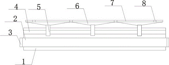
[0015] Such as figure 1 The preferred embodiment of the road drainage structure of the present invention shown includes a concrete slab 1, and a guide pipe 2 is installed horizontally on the concrete slab 1, and the two ends of the guide pipe 2 pass through the concrete slab 1 and are arranged. A pipe plug 3 is connected, and the pipe plug 3 is hinged on the diversion pipe 2. A water collecting part 4 is arranged horizontally above the diversion pipe 2 and inside the concrete slab 1, and a drainage joint 5 is vertically arranged on the water collecting part 4 to drain water. The joint 5 communicates with the water collecting part 4, and the top of the drainage joint 5 ...


PUM


Abstract

The invention discloses a road drainage structure which comprises a concrete board. A flow guide pipe is transversely installed on the concrete board. The two ends of the flow guide pipe penetrate the concrete board and connected with pipe plugs. The pipe plugs are hinged to the flow guide pipe. A water collection piece is transversely arranged above the flow guide pipe and located in the concrete board. Drainage joints are vertically arranged on the water collection piece and communicated with the water collection piece. Water penetration layers are connected to the tops of the drainage joints. Each water penetration layer is of a reversed-triangle structure. The upper surface of each water penetration layer is located on a road foundation layer. Connecting pipes are arranged in the water penetration layers and vertically arranged on the water penetration layer. The road drainage structure is good in drainage effect and is used for municipal road drainage, a drainage device can be prefabricated, a construction period is shortened, labor intensity is relieved, cost is reduced, and road load bearing strength is not affected; meanwhile, the drainage requirements of different regions and different rainfall volumes can be met by adjusting the diameter of laid drainage pipes and the void ratio of graded broken stone.

Description

technical field [0001] The invention relates to a drainage structure, in particular to a road drainage structure. Background technique [0002] The surface of modern cities is gradually covered by reinforced concrete houses and dense impermeable pavement. When heavy rain is caused, the surface runoff increases sharply and peaks soon, which increases the burden on the urban drainage system and is one of the main causes of urban waterlogging disasters. The use of drainage pavement is conducive to alleviating the occurrence of urban waterlogging disasters. Drainage pavement The pavement is paved with a large-porosity pavement mixture with a porosity of about 15% to 25%. After the rain falls on the ground, it will not immediately form runoff on the road surface, but will flow into the pores of the pavement material and temporarily remain in the pavement. Therefore, it can effectively relieve the burden on the urban drainage system. However, the general drainage structure has p...

Claims


Application Information

Patent Timeline
Patent Type & Authority Applications(China)
IPC IPC(8): E01C5/06E01C11/24E01C3/06E01F5/00
Inventor 缪家戌
Owner CHENGDU KECHUANG JIASI TECH
Why Eureka
Try Eureka