Compressor and pipeline system damping energy-saving apparatus thereof

An energy-saving device and compressor technology, applied to compressors and their piping system vibration reduction and energy-saving devices, reciprocating compressors and their piping system vibration reduction and energy-saving devices, outlet buffer tanks or buffers or shock absorbers, compressor inlets, In the field of resonant internals, it can solve problems such as complex airflow pulsation mechanism, insignificant effect, imperfect theory and design methods, etc.

Inactive Publication Date: 2015-10-21
刘友宏
View PDF8 Cites 4 Cited by
  • Summary
  • Abstract
  • Description
  • Claims
  • Application Information

AI Technical Summary

Problems solved by technology

The ideal orifice plate is to convert the pressure standing wave in the pipe section into a traveling wave, thereby reducing the pressure unevenness in the pipe section. Sensitivity to environmental changes, so sometimes the orifice plate has a certain effect, but most of the effects are not significant, and become a pure resistance element, wasting a lot of advanced mechanical energy in vain
[0008] Because the characteristics of compressor airflow pulsation, and its generation and propagation process are affected by many important factors, no effective solution to airflow pulsation has been found at home and abroad. At the same time, because the mechanism of airflow pulsation is complex, its theory and design methods are not yet perfect.

Method used


Image

  • Compressor and pipeline system damping energy-saving apparatus thereof
  • Compressor and pipeline system damping energy-saving apparatus thereof
  • Compressor and pipeline system damping energy-saving apparatus thereof

Examples


Embodiment Construction

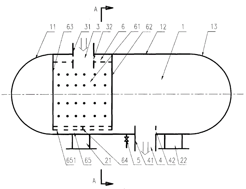
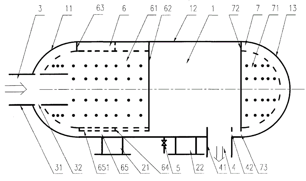
[0039] Figure 1 to Figure 2 Shown is a compressor installed with a resonant inner part that dampens pressure pulsation and speed pulsation and its pipeline system vibration reduction and energy saving device. The implementation and / or operation of all vibration damping and energy saving devices installed with the compressor and its piping system will be given in the detailed description of the first preferred embodiment of the present invention.

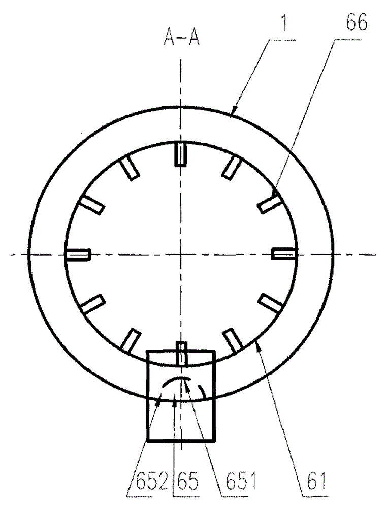
[0040] Will figure 1 Secondary six parts: 1) Right head ( figure 1 Symbol 13; 2) cylinder ( figure 1 Middle symbol 12); 3) left and right support ( figure 1 Chinese symbols 21, 22); 4) import ( figure 1 middle symbol 3); 5) exit ( figure 1 Middle symbol 4); 6) Sewage outlet ( figure 1 Middle symbol 5), welded in sequence to form a space structure with a support at the left end. Then the resonant internals ( figure 1 Components in symbol 6): 1) cover plate ( figure 1 Middle symbol 61); 2) right panel ( figure 1 Middle symbo...


PUM


Abstract

The invention relates to a compressor and a pipeline system damping energy-saving apparatus thereof. The pipeline system damping energy-saving apparatus comprises 1) a shell; 2) a left supporting seat and a right supporting seat; 3) an inlet; 4) an outlet; 5) a sewage draining outlet; and 6) an attenuation pressure pulsation and speed pulsation resonance inner member. The first part, the second part, the third part, the fourth part, and the fifth part are connected in sequence to form a hollow space structure, the sixth part is arranged in the space structure, the attenuation pressure pulsation and speed pulsation resonance inner member is formed by a cover plate and side plates, the attenuation pressure pulsation and speed pulsation resonance inner member and an inner wall surface of the shell form a hollow structure, a plurality of separating plates can be arranged or not arranged in the hollow structure, a plurality of through holes can be arranged or not arranged on the cover plate and the side plates, the through holes are connected or not connected with fine pipes with the same internal diameter, and the resonance inner member is arranged at the gravity bottom of the apparatus and is provided with a discharge drainage channel. The space of a harmonic oscillator is determined via calculation and analysis, and the resonant frequency is equal to the pulsation main frequency so that compressor main-frequency airflow pulsation waves are effectively blocked or attenuated or not reflected by the apparatus.

Description

technical field [0001] The invention belongs to the technical field of equipment in industries such as energy, petroleum, chemical industry, metallurgy, mining, and medicine, and specifically relates to a compressor and a piping system vibration reduction and energy-saving device. [0002] Furthermore, the invention relates to a resonant internal with damping of pressure pulsations, velocity pulsations. [0003] In addition, the present invention relates to a reciprocating compressor used in energy, petrochemical, chemical fertilizer and other industries and its piping system vibration reduction and energy saving device. [0004] In addition, the present invention relates to a compressor inlet and outlet buffer tank or buffer or shock absorber used in energy, petrochemical, chemical fertilizer, mining, steel, medicine, aerospace and other industries. Background technique [0005] The suction and exhaust process of the compressor has pulsation characteristics, which will cau...

Claims


Application Information

Patent Timeline
Patent Type & Authority Applications(China)
IPC IPC(8): F04B39/00
CPCY02P20/10
Inventor 刘友宏
Owner 刘友宏
Why Eureka
Try Eureka