Positioning method for blocking position of ore slurry conveying pipeline

A technology for transportation pipelines and pipelines, which is applied in the field of transportation control, can solve problems such as high operating costs, scrapped pipelines, and economic losses of enterprises, and achieve the effects of reducing workload, low operating costs, and less hardware equipment

Inactive Publication Date: 2015-10-21
YUNNAN DAHONGSHAN PIPELINE
View PDF4 Cites 13 Cited by
  • Summary
  • Abstract
  • Description
  • Claims
  • Application Information

AI Technical Summary

Problems solved by technology

These methods all need to excavate the pipeline to expose, and continuously test the degree of deformation of the pipeline along the pipeline or drill holes to observe the fluid state. The workload is large, the time is long, and the operation cost is high.
Once a blockage accident occurs in the slurry transportation pipeline, if it is not found in time, it will cause pipeline rupture, environmental pollution...

Method used


Image

  • Positioning method for blocking position of ore slurry conveying pipeline
  • Positioning method for blocking position of ore slurry conveying pipeline

Examples


Embodiment 1

[0029] The method for locating the blockage position of the slurry transportation pipeline of the present invention includes the following steps:

[0030] The method for blocking the position of the slurry transportation pipeline of the present invention includes the following steps:

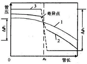
[0031] (1) When the slurry is transported normally, the hydraulic gradient curve of the entire pipeline is curve 1, and the pressure difference at both ends of the pipeline is △p 1 ;

[0032] (2) When the distance from the starting point of the pipeline χ 0 After a partial blockage occurs, the pipeline before the blockage point is under pressure, and the pipe section after the blockage point loses part of its energy supply, and its hydraulic slope curve is curve 2;

[0033] (3) When the distance from the starting point of the pipeline χ 0 After a complete blockage occurs, the pipeline is holding back pressure before the blockage point, and the slurry in the pipeline basically stops flowing, and the pipe ...

Embodiment 2

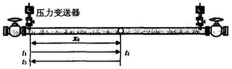
[0050] A domestic slurry pipeline was demagnetized in 2014 because the slurry was not demagnetized by a demagnetizer. At that time, the pumping station of the slurry pipeline was shut down due to thunderstorms. When the slurry was shut down and restarted, the outlet pressure was found to rise sharply. Personnel experience judges that the pipeline is blocked. The inner diameter D of the slurry pipeline is 253mm, and the slurry density ρ is 2073kg / m 3, The elastic modulus E of the pipeline material is 2.07*10^11pa, the wall thickness e of the pipeline is 10mm, the distance L between the No. 1 pumping station and the downstream pumping station is 12.5 kilometers, and the bulk elastic modulus of the conveying slurry measured by experiments is 27*10^ 7pa, the negative pressure wave velocity measured by theoretical calculation is about 989m / s, and then through the SCADA computer program, the time difference Δt between the two transmissions of the positive pressure wave to the upstream ...


PUM

PropertyMeasurementUnit
Densityaaaaaaaaaa

Abstract

The invention provides a positioning method for blocking positions of an ore slurry conveying pipeline, and relates to a conveying control method, and especially relates to a method for determining blocked points in blocking management in an ore slurry conveying process. A positive pressure wave method is used to detect blocking of a pipeline according to violent changes of pressure differences of two ends of the pipeline before the pipeline is blocked and after the pipeline is blocked, and a principle and a method for determining ore slurry pipeline blocking positions by using positive pressure waves in a pipeline hydraulic surge process are provided for the first time. The method is advantaged by few required devices, low operation cost, and simple operation, and is better than existing pipeline blocking position determination methods.

Description

Technical field [0001] The invention relates to a conveying control method, in particular to a method for determining a blockage point when the conveying management blockage during the slurry conveying process. Background technique [0002] In the slurry pipeline, due to the influence of factors such as the non-demagnetization of the slurry, the size of the slurry, the substandard delivery concentration and other factors, the slurry is easy to form magnetic stranding in the pipeline or the coarse particle slurry is deposited on the bottom of the pipeline, causing the transmission pressure to increase. Adjustment will cause the pipeline to be blocked when the machine stops and restarts. In addition, during the pigging process of the slurry pipeline, the impurities inside the pipeline will accumulate, which will easily cause the pig to block. If it is not handled in time, it will cause huge economic losses. At present, the detection technology of pipeline blockage position mainly ...

Claims


Application Information

Patent Timeline
IPC IPC(8): F17D5/00F17D3/01
Inventor 王长勇普光跃张晓南李学鑫
Owner YUNNAN DAHONGSHAN PIPELINE
Why Eureka
Try Eureka