Rapid and accurate computation method for large-scale MIMO array antenna far-field radiation field

An array antenna and fast computing technology, applied in computing, special data processing applications, instruments, etc., can solve the problems of memory and computing time consumption, and the inability to quickly and accurately implement antenna radiation field calculations

Active Publication Date: 2015-10-21
THE PLA INFORMATION ENG UNIV
View PDF4 Cites 23 Cited by
  • Summary
  • Abstract
  • Description
  • Claims
  • Application Information

AI Technical Summary

Problems solved by technology

However, due to the limitation of the computing power of a single computer, when the scale of the array antenna is too large, any full-wave simulation method, even the current hi

Method used


Image

  • Rapid and accurate computation method for large-scale MIMO array antenna far-field radiation field
  • Rapid and accurate computation method for large-scale MIMO array antenna far-field radiation field
  • Rapid and accurate computation method for large-scale MIMO array antenna far-field radiation field

Examples


Embodiment 1

[0043] Example 1: Combination Figure 1-Figure 2 , An accurate and fast calculation method for the far-field radiation field of a massive MIMO array antenna. The calculation method includes the following steps:

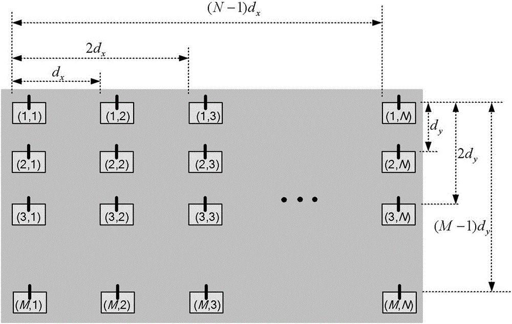
[0044] Step 1: Determine the element spacing parameter d of the M×N element planar array antenna x ,d y , Where d x Is the element spacing in the x direction of the planar array antenna, d y Is the element spacing of the planar array antenna in the y direction, reference for M×N element planar array antenna figure 1 Shown.

[0045] Step 2: Solve the relationship between the incident field and the scattered field of the element antenna. The relationship is:

[0046] Considering the incident plane wave, the incident field of the antenna element And scattered field According to the spherical vector wave form, there are

[0047] E i i n c = X m , n , i ( a m n M m n + b m n N m n ) - - - ...

Embodiment 2

[0073] Embodiment 2: In the following, in conjunction with Table 1, taking an 8×8 planar array as an example, the present invention will be further described.

[0074] 1

2

3

4

5

6

7

8

9

10

11

12

13

14

15

16

17

18

19

20

21

22

23

24

25

26

27

28

29

30

31

32

33

34

35

36

37

38

39

40

41

42

43

44

45

46

47

48

49

50

51

52

53

54

55

56

57

58

59

60

61

62

63

64

[0075] Table 1

[0076] First, determine the structural parameters of the 8×8 element planar array antenna.

[0077] Second, determine the scale of the environmental sub-array in the array;

[0078] Considering the three distribution characteristics in the x-direction and y-direction: edge, sub-edge and array distribution, as well as the symmetry of the planar array antenna structure, a total of 9 sub-arrays need to be extracted, as shown in Table 2:

[0079]

[0080] Table 2

[0081] Again, calculate the far-field radiation pattern of the 9 sub-array elements in sequence;

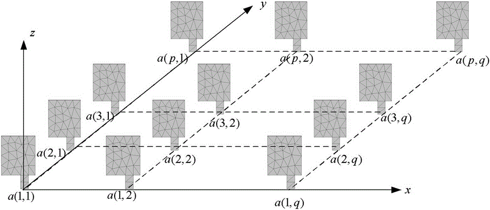
[0082] Assuming that the number of element antennas is p×...


PUM


Abstract

The present invention belongs to the field of electromagnetic value computing, and particularly relates to a rapid and accurate analysis method for large-scale MIMO array antenna far-field radiation. The method comprises: determining a structural parameter of an M*N-element plane array antenna; computing a relationship between an incident field and a scattered field of an element antenna; according to mutual coupling characteristics among element antennas, selecting a sub-array form and size of an extraction unit on an array environment condition; for an antenna sub-array of the extraction unit, computing a unit far-field radiation pattern of the sub-array; and according to the unit far-field radiation patterns of the array and a superposition principle, computing an array antenna far-field radiation pattern. According to the invention, by utilizing the accuracy of mutual coupling computation, the problems that the use of such methods as the moment method, the finite element method and the finite difference time domain (FDTD) method are limited by computing capacity of a single computer, and when the scale of the array antenna is too large, rapid and accurate computation of the antenna radiation field cannot be implemented with a full wave simulation method because of large consumption of memory and computing time, are effectively solved. The method provided by the invention is capable of analyzing the radiation pattern of a large and conformal array antenna, and has higher synthesizing accuracy and higher analysis speed.

Description

Technical field [0001] The invention belongs to the field of electromagnetic numerical calculations, and specifically relates to an accurate and fast analysis method for the far-field radiation of a large-scale MIMO array antenna solved by an iterative scattering algorithm. Background technique [0002] The massive antenna array system (namely Massive MIMO) is considered to be the most potential transmission technology for 5G in the future, and it is an extension and extension of the MIMO technology in the existing 4G network. Massive MIMO system has a very good effect in increasing system capacity, improving communication quality and versatility of equipment in complex environments. It conforms to the current development trend of RF components closer to the antenna, reduces maintenance costs and energy costs, while further improving network performance and deployment flexibility, and plays an important role in the fifth-generation mobile communication system. Massive MIMO activ...

Claims


Application Information

Patent Timeline
IPC IPC(8): G06F17/50
Inventor 陈国虎朱明林陈宏伟钟州刘起坤黄开枝安娜杨梅樾韩乾陈丹
Owner THE PLA INFORMATION ENG UNIV
Why Eureka
Try Eureka