A Series-Parallel Combination Structure Envelope Tracking Power Supply
A technology of combined structure and power tracking, applied in electrical components, regulating electrical variables, instruments, etc., to achieve the effect of improving overall efficiency and reducing power loss
- Summary
- Abstract
- Description
- Claims
- Application Information
AI Technical Summary
Problems solved by technology
Method used
Image
Examples
Embodiment 1
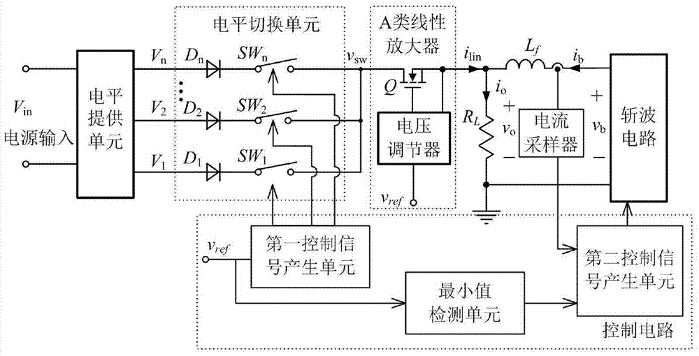
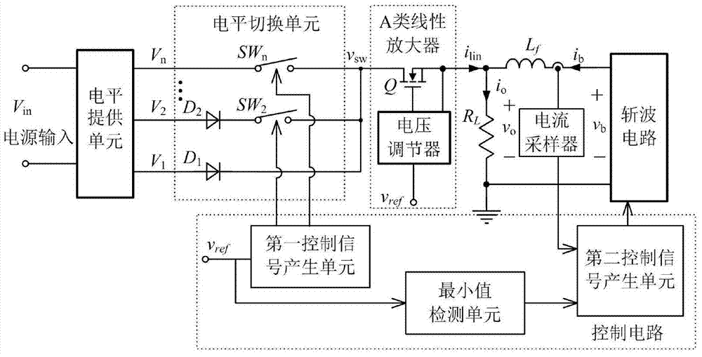
[0037] Accompanying drawing 1 has provided the schematic diagram of the series-parallel combination structure of the envelope tracking power supply adopting the first kind of current control strategy, and accompanying drawing 1 (a) has provided the complete circuit structure, wherein the highest level diode D n and the lowest level switching tube SW 1 Can omit as shown in accompanying drawing 1 (b).
[0038]Among them, the level supply unit converts the input voltage into the required multi-level output, and there are many ways to realize it. Figures 3(a) and 3(b) show two of the available methods. According to the characteristics of the input reference signal, the first control signal generation unit compares it with multiple set amplitudes to obtain the control signal of the switch tube of the multi-level switching unit, so as to provide the previous level to the multiple levels output by the unit A step wave voltage modulated to fit the shape of the output voltage power...
Embodiment 2
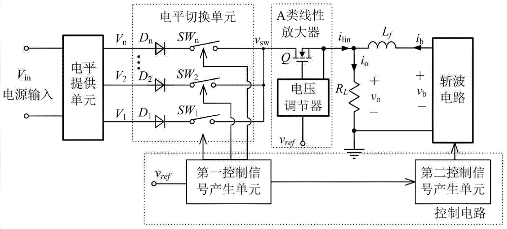
[0042] Accompanying drawing 2 has given the schematic diagram of the series-parallel combination structure of the envelope tracking power supply adopting the second current control strategy, and accompanying drawing 2 (a) has provided the complete circuit structure, wherein the diode of the highest level D n and the lowest level switching tube SW 1 It can be omitted as shown in accompanying drawing 2 (b).
[0043] In this example, the realization of the level supply unit and the switching unit is the same as that of Example 1, and the control strategy for the chopper circuit is different. In the second current control method, the output current of the chopper circuit is open-loop control, and the reference signal is directly calculated, compared with the preset value to control the action of the switch tube in the corresponding chopper circuit. Particularly, when the chopping circuit adopts the scheme shown in accompanying drawing 5 (B), this preset value is v ref / 2. a...
PUM
 Abstract
Description
Claims
Application Information
 - R&D
- Intellectual Property
- Life Sciences
- Materials
- Tech Scout
- Unparalleled Data Quality
- Higher Quality Content
- 60% Fewer Hallucinations
Browse by: Latest US Patents, China's latest patents, Technical Efficacy Thesaurus, Application Domain, Technology Topic, Popular Technical Reports.
© 2025 PatSnap. All rights reserved.Legal|Privacy policy|Modern Slavery Act Transparency Statement|Sitemap|About US| Contact US: help@patsnap.com


