Multi-axis unmanned aerial vehicle

An unmanned aerial vehicle and rotor technology, applied in the field of aircraft, can solve the problems of single application, low load, easy damage, etc., and achieve the effect of convenient operation, high application value and stable structure

Inactive Publication Date: 2015-10-28
SUN HAWK HENAN AVIATION IND CO LTD
View PDF5 Cites 3 Cited by
  • Summary
  • Abstract
  • Description
  • Claims
  • Application Information

AI Technical Summary

Problems solved by technology

[0007] The purpose of this application is to provide a multi-axis unmanned aerial vehicle with a large load, long endurance, and various applications, so as to solve the technical problems that the existing multi-axis unmanned aerial vehicle is applicable to a single, easy to damage, low load, and short flight time

Method used


Image

  • Multi-axis unmanned aerial vehicle
  • Multi-axis unmanned aerial vehicle

Examples


Embodiment 1

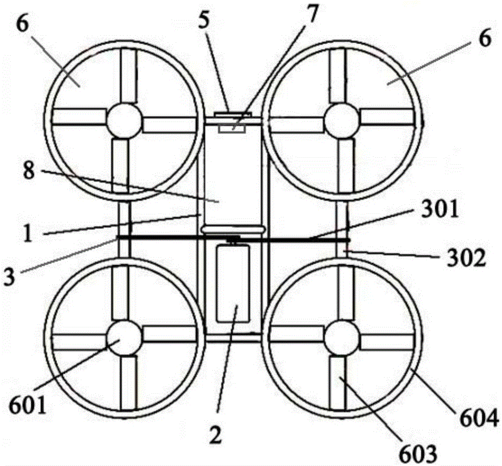
[0036] This embodiment provides a multi-axis unmanned aerial vehicle, which is characterized by comprising: a frame 1 and a power generating device 2, a power transmission device 3, a pitch changing device 4, a control device 5, and a plurality of rotors arranged on the frame Device 6, in which,

[0037] The power generating device 2 is connected to the power transmission device 3 for providing flight power;

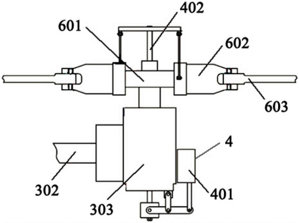
[0038] The power transmission device 3 includes a transmission belt 301, a transmission shaft 302, and a gear box 303 that are connected in sequence. The transmission belt 301 is connected to the power generation device 2, and the gear box 303 is connected to the rotor device 6. connection;

[0039] The rotor device 6 includes a rotor head 601, a propeller hub 602, and a propeller 603 that are connected in sequence, and the rotor head 601 is connected to the gear box 303;

[0040] The pitch changing device 4 includes a steering gear 401 and a pitch changing rod 402, the steerin...


PUM


Abstract

The invention discloses a multi-axis unmanned aerial vehicle. The multi-axis unmanned aerial vehicle comprises a rack, a power generation device, a power transmission device, a variable-pitch device, a control device and multiple rotor devices, wherein the power generation device, the power transmission device, the variable-pitch device, the control device and the multiple rotor devices are arranged on the rack; the power generation device is connected with the power transmission device and used for supplying flight power; the power transmission device comprises a transmission belt, a transmission shaft and gear boxes, the transmission belt, the transmission shaft and the gear boxes are sequentially connected, the transmission belt is connected with the power generation device, and the gear boxes are connected with the rotor devices; each rotor device comprises a rotor head, a propeller hub and screw propellers, the rotor head, the propeller hub and the screw propellers are sequentially connected; the rotor heads and the gear boxes are connected; the variable-pitch device comprises a variable-pitch rod and a steering engine, the variable-pitch rod is connected with the rotor heads, and the steering engine is connected with the gear boxes; the control device is connected with the power generation device, the power transmission device, the rotor devices and the variable-pitch device respectively.

Description

Technical field [0001] This application relates to the technical field of aircraft, and specifically to a multi-axis unmanned aerial vehicle. Background technique [0002] At present, the traditional helicopter is a single-rotor with a tail rotor layout, relying on the rotation of the main rotor to provide lift, and the high-speed rotation of the tail rotor produces a lateral push-pull force to overcome the anti-torque generated by the main rotor. This layout has a simple structure and mature technology. It can be flexibly used to manufacture helicopters of various specifications, and the operation is relatively simple. However, the tail beam causes a large parking area, the load-bearing tail beam and the long-distance tail rotor drive shaft system are easily damaged, the collision risk is high, the hovering performance is unstable, the tail rotor is easily damaged by foreign objects, causing major accidents, and the tail rotor needs to be consumed. About 15% of engine power. [...

Claims


Application Information

Patent Timeline
Patent Type & Authority Applications(China)
IPC IPC(8): B64C27/08B64C27/68B64C27/32B64D35/04
CPCB64C27/04B64C27/08B64C27/12B64D35/00
Inventor 陶亮申守健秦立新
Owner SUN HAWK HENAN AVIATION IND CO LTD
Why Eureka
Try Eureka