
Intelligent signal amplification apparatus and method for foundation piles ultrasonic testing equipment

An ultrasonic and intelligent technology, applied in the field of ultrasonic foundation pile integrity detection, can solve the problems of large A/D conversion error, signal peak value exceeding A/D, small signal, etc., achieve large A/D conversion accuracy, and improve sampling accuracy. Effect

Inactive Publication Date: 2015-10-28
CENT SOUTH UNIV
View PDF7 Cites 3 Cited by
  • Summary
  • Abstract
  • Description
  • Claims
  • Application Information

AI Technical Summary

Problems solved by technology

The disadvantages of this method are as follows: (1) In the field test, it is usually impossible to accurately estimate the peak value of the signal waveform, and it is easy to cause the peak value of the signal to exceed the A / D range due to too large magnification, or to enter the A / D due to too small magnification. The signal is too small, and the signal cannot be clearly expressed; (2) Since this method adjusts the amplification factor according to the peak value of the entire signal waveform, the A / D conversion accuracy of the weak signal part in the entire signal waveform is low, and it is easy to lose important judgments Information, and even a large A / D conversion error, resulting in the inability to accurately identify the quality of foundation piles
[0003] The A / D sampling frequency required by the ultrasonic foundation pile integrity detection method is generally above 10MHz, but the response and stabilization time of the current programmable gain amplifier is about several microseconds, and it cannot directly replace the amplification in the existing acoustic transmission method alone. Module, used in ultrasonic foundation pile integrity testing equipment

Method used


Image

  • Intelligent signal amplification apparatus and method for foundation piles ultrasonic testing equipment
  • Intelligent signal amplification apparatus and method for foundation piles ultrasonic testing equipment
  • Intelligent signal amplification apparatus and method for foundation piles ultrasonic testing equipment

Examples


Embodiment Construction

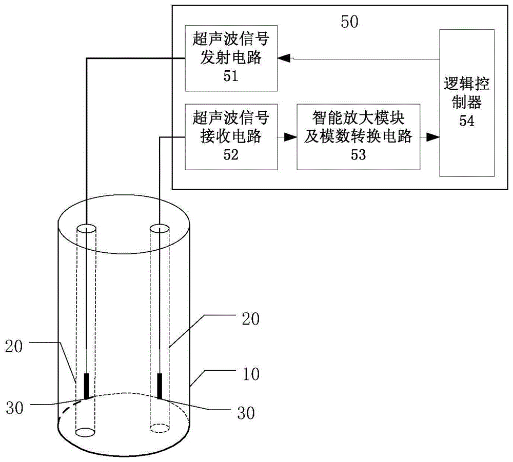
[0049] Such as figure 1 Shown is a schematic diagram of the application method of the device of the present invention in ultrasonic foundation pile integrity detection, wherein 10 is a foundation pile to be tested, 20 is a pre-embedded acoustic measuring tube, 30 is an acoustic wave probe for foundation pile detection, and 50 is ultrasonic emission / reception Control unit; the ultrasonic transmission / reception control unit 50 includes an ultrasonic transmission circuit 51, an ultrasonic signal receiving circuit 52, an intelligent amplification module and an analog / digital conversion circuit 53, and a logic controller 54; the intelligent amplification module and an analog / digital conversion The circuit 53 is the device of the present invention. This module obtains the converted ultrasonic electrical signal from the ultrasonic signal receiving circuit 52, amplifies the signal, and sends the generated digital waveform signal to the logic controller 54 after analog / digital conversio...


PUM


Abstract

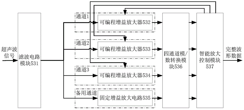
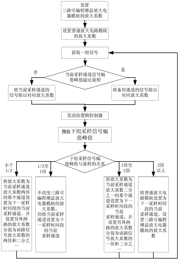
The invention discloses an intelligent signal amplification apparatus and method for foundation piles ultrasonic testing equipment. The apparatus includes a filter circuit, a three-way programmable gain amplifier, a fixed gain amplifier, a four-channel A / D converter circuit module and an intelligent zoom control module. The method provided by the invention circularly and alternately adjust the amplification factor of the three-way programmable gain amplifier, can effectively always maintain the sampled signal between half of the A / D sampling range and the maximum range of the analog / digital conversion module, so as to achieve the largest possible A / D conversion accuracy without loss of signal. The apparatus and method can ensure that any sampling period in the measurement process has at least one way of stable programmable gain amplifier, so that the adjustment of amplification coefficient of the programmable gain amplifier does not affect the reliability and integrity of the final output data.

Description

Technical field: [0001] The invention belongs to the field of ultrasonic foundation pile integrity detection, in particular to an intelligent signal amplification device and method for foundation pile ultrasonic detection equipment. Background technique: [0002] At present, the pile foundation structure is widely used in the construction field. The integrity of the pile foundation has a very important impact on the safety of the building. The acoustic transmission method is one of the most widely used methods in today's pile foundation integrity detection. The method is to put a plurality of acoustic wave probes into the pre-buried parallel acoustic measuring tubes, one probe emits and the other probes receive; the probe converts the acoustic wave signal into an electrical signal, and then obtains a digital signal after filtering, amplifying, and A / D sampling processing. Signal waveform, and finally judge the concrete quality between the two probes by analyzing the signal w...

Claims


Application Information

Patent Timeline
Patent Type & Authority Applications(China)
IPC IPC(8): G01N29/44
Inventor 倪炜陈伟万亚洲
Owner CENT SOUTH UNIV
Learn More