A self-powered solar controller

A solar controller, self-powered technology, applied in control/regulation systems, instruments, photovoltaic power generation, etc., can solve the problems of unusable solar controller, high cost, complicated circuit, etc., to improve photoelectric conversion efficiency, avoid power Oscillating, easy-to-use effects

Active Publication Date: 2017-04-12
ANHUI POLYTECHNIC UNIV
View PDF6 Cites 0 Cited by
  • Summary
  • Abstract
  • Description
  • Claims
  • Application Information

AI Technical Summary

Problems solved by technology

Most of the existing solar controllers are systems composed of microprocessors such as single-chip microcomputers or DSPs. The maximum power point tracking algorithms such as disturbance observation method, conductance incremental method and linear approximation method are realized by software algorithms. Most of these solar controllers have complex circuits. , The cost is more expensive, and it is easy to generate power oscillation near the maximum power point, resulting in unnecessary energy loss
There are also some low-power solar controllers. In order to save costs, a simple constant voltage method is used to track the maximum power point of the photovoltaic cell. This method cannot accurately track the maximum power point of the photovoltaic cell, resulting in a decrease in the photoelectric conversion efficiency of the photovoltaic cell.
On the other hand, the existing solar controllers all need an additional power supply to power the controller itself, and some even need dual power supplies for power supply, making the solar controller unusable in places where power supply is inconvenient

Method used


Image

  • A self-powered solar controller
  • A self-powered solar controller
  • A self-powered solar controller

Examples


Embodiment Construction

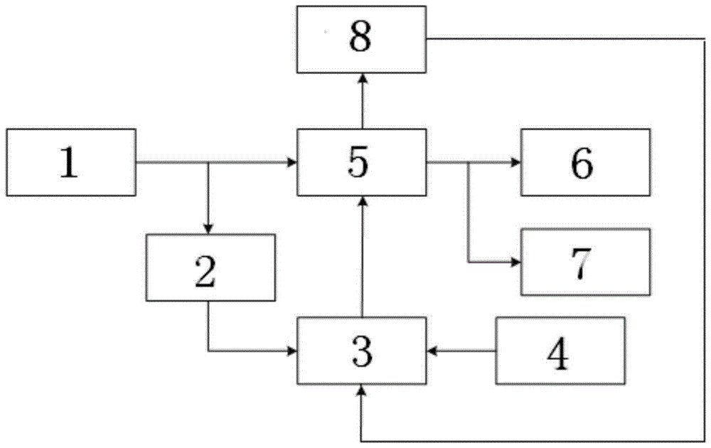
[0025] Such as figure 1 As shown, the present invention includes that the voltage output by the photovoltaic cell 1 is reduced by the DC-DC conversion module 5 to supply power to the load circuit module 6 and the battery charging circuit 7. The photovoltaic cell 1 is connected to the current acquisition module 2 at the same time; the controller is also provided with illuminance The acquisition module 4 transmits the collected illumination information and the current information of the current acquisition module 2 to the control circuit module 3, and the control circuit module 3 outputs a PWM signal to drive the power switch device of the DC-DC conversion module 5 to work.

[0026] Current acquisition module 2, which uses high-precision, high-power, and low-resistance current sensing resistors to convert current signals into voltage signals to improve sampling accuracy and reduce costs. The current acquisition module also regulates the collected voltage through a differential propo...


PUM


Abstract

The invention discloses a self-powered solar controller, which is characterized by comprising a photovoltaic cell, wherein voltage output by the photovoltaic battery is subjected to voltage reduction through a DC-DC (direct current-direct current) conversion module, and then provides power for a load circuit and a storage battery charging circuit; the photovoltaic battery is connected with a current sampling module at the same time; the controller is also provided with an illumination intensity collecting module; illumination information collected by the illumination intensity collecting module and current information collected by the current collecting module are jointly transmitted to a control circuit module; the control circuit module output PWM (pulse width modulation) signals to drive a power switch device of the DC-DC conversion module to work. Through the adoption of the structure, the connection of additional power supplies is avoided, so that the solar controller can be used in places such as outer spaces, seas and fields in which the power supply is inconvenient. The size is small; the cost is low; the maximum power point of the photovoltaic battery can be accurately tracked; the power oscillation caused by an ordinary maximum power point tracking algorithm is avoided; the photovoltaic conversion efficiency of the photovoltaic cell is improved; in addition, the use is convenient and flexible.

Description

Technical field [0001] The invention relates to solar photovoltaic cell power generation technology, in particular to a self-powered solar controller. Background technique [0002] Energy is an important material basis for the survival and development of human society. At present, the world's energy is still dominated by fossil energy such as coal, oil and natural gas. However, these fossil energies are non-renewable resources, and these fossil energies will produce a lot of pollutants during the use process, which will cause great damage to the human ecological environment. As a kind of clean energy, solar energy has gradually become an important part of human energy use. [0003] The solar controller is an automatic control device used in the field of solar photovoltaic cell power generation to control the solar photovoltaic cell to supply power to the load and charge the battery. Most of the existing solar controllers are systems composed of single-chip microcomputers or DSPs...

Claims


Application Information

Patent Timeline
Patent Type & Authority Patents(China)
IPC IPC(8): G05F1/67H02J3/38H02M3/156
CPCY02E10/56
Inventor 汪石农陈其工高文根吴飞吴浙勋
Owner ANHUI POLYTECHNIC UNIV
Why Eureka
Try Eureka