Floating passive cooling device and system of spent fuel pool in nuclear power plant

A spent fuel pool and passive cooling technology, applied in the field of nuclear power, can solve the problems of only 72 hours of effective time, limited heat absorption area, etc., to improve heat removal capacity, reduce radiation dose, and heat exchange The effect of high coefficient

Active Publication Date: 2015-10-28
CHINA NUCLEAR POWER TECH RES INST CO LTD +2
View PDF5 Cites 8 Cited by
  • Summary
  • Abstract
  • Description
  • Claims
  • Application Information

AI Technical Summary

Problems solved by technology

[0005] 1. The cooling effectiveness of the spent fuel pool depends on the effectiveness of the AC power supply. If the power supply cannot be restored in time after an accident, the spent fuel will be exposed
In situations like the Fukushima nuclear accident, the safety of spent fuel cannot be guaranteed;
[0006] 2. In the passive cooling design of the spent fuel pool of the existing nuclear power plant (such as AP1000), the removal of the decay heat of the spent fuel pool relies on passive safe water supply, and the source of non-dynamic safe water supply is limited, so it implements passive cooling. The effective time of cooling is only up to 72 hours;
[0007] 3. In the passive cooling design of the spent fuel pool of the existing nuclear power plant (such as AP1000), the start-up and adjustment of the safety injection system depend on the 1E-level direct current and the actions of the operator. The f

Method used


Image

  • Floating passive cooling device and system of spent fuel pool in nuclear power plant
  • Floating passive cooling device and system of spent fuel pool in nuclear power plant

Examples


other Embodiment approach

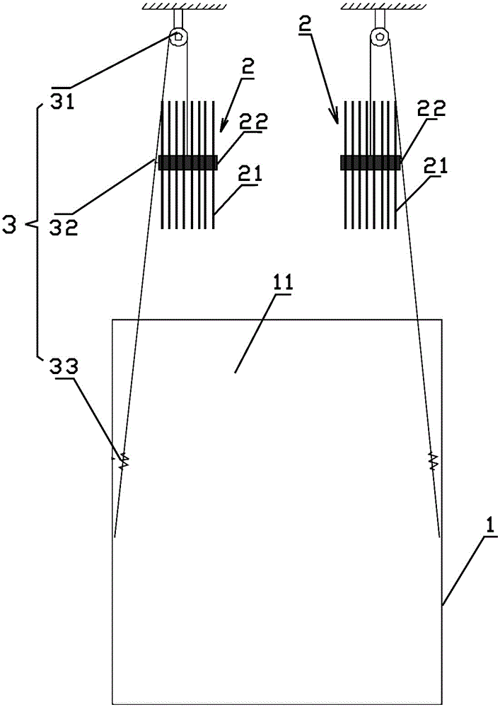
[0043] In other embodiments, the heat exchange tube assembly 2 can be stacked and assembled, that is, a large component is formed by assembling multiple groups. For example, four or eight heat exchange tube assemblies 2 can be assembled and fixed together. Such setting can further enhance the stability of the passive cooling device of the floating spent fuel pool of the nuclear power plant standing vertically on the water surface, and can also enhance its heat dissipation performance.

[0044] Preferably, multiple sets of heat exchange tube assemblies 2 can stand vertically on the liquid surface 11 of the spent fuel pool 1 .

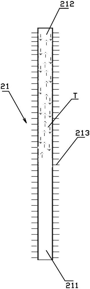
[0045] It should be noted that the hollow cylindrical sealed barrel of the grid 22 can also play the following functions. When multiple sets of heat exchange tube assemblies are assembled, the cylindrical grid 22 can reduce heat exchange with adjacent heat transfer tubes. Tangent lines or points of contact between tube assemblies, thereby reducing the p...


PUM

PropertyMeasurementUnit
Boiling pointaaaaaaaaaa

Abstract

The invention discloses a floating passive cooling device of a spent fuel pool in a nuclear power plant. The passive cooling device at least comprises a heat exchange tube assembly. The heat exchange tube assembly comprises a plurality of heat exchange tubes and a grillwork, wherein the heat exchange tubes are filled with a certain quantity of cooling working media, and certain negative pressure is kept inside each heat exchange tube; the heat exchange tubes are evenly arranged on the grillwork in an equidistant mode, and the grillwork can generate a certain amount of buoyancy in liquid of the spent fuel pool so that the heat exchange tube assembly can float on the liquid level of the spent fuel pool. The portion, placed under the liquid level of the spent fuel pool, of each heat exchange tube is a heat absorption end, and the portion, placed over the liquid level of the spent fuel pool, of each heat exchange tube is a heat release end. The cooling working media are low boiling point working media. The invention further discloses a floating passive cooling system of the spent fuel pool in the nuclear power plant. By implementing the floating passive cooling device and system of the spent fuel pool in the nuclear power plant, operating can be conducted in a completely passive mode, so that safety is improved; the heat radiating area is further increased, and the heat removal capacity is greatly improved; the heat transfer working media can be recycled, and the device and system are environmentally friendly and stable.

Description

technical field [0001] The invention relates to the field of nuclear power, in particular to a passive cooling device and system for a floating spent fuel pool of a nuclear power plant. Background technique [0002] After the fuel in the core of a nuclear power plant reaches burnup depth, it is removed from the reactor and moved to the spent fuel pool (SFP) for storage. There are two types of existing spent fuel pool storage, one is dry storage and the other is wet storage, and the latter is widely used at present. The anti-seismic structural design of SFP can ensure the integrity of the pool and fuel safety; the depth of the pool water covering the spent fuel provides sufficient radiation protection for the staff; the design of the fuel grid and soluble poison (boron) can ensure the subcritical safety of the spent fuel; The spent fuel pool cooling and purification system (SFS) provides sufficient cooling for the spent fuel pool water to remove decay heat. [0003] The cur...

Claims


Application Information

Patent Timeline
IPC IPC(8): G21C15/18
CPCG21C15/18Y02E30/30
Inventor 杨江王婷卢向晖崔军庄程军林维青林建树林支康方思远蔡永铁陶俊毛玉龙蒋晓华
Owner CHINA NUCLEAR POWER TECH RES INST CO LTD
Why Eureka
Try Eureka