
Camera and robot relative pose calibration method based on pixel space optimization

A technology of relative pose and calibration method, applied in manipulators, program-controlled manipulators, manufacturing tools, etc., can solve the problems of low accuracy, error, noise sensitivity, etc.

Active Publication Date: 2015-11-04
ZHEJIANG UNIV
View PDF6 Cites 38 Cited by
  • Summary
  • Abstract
  • Description
  • Claims
  • Application Information

AI Technical Summary

Problems solved by technology

The previous method attributed this kind of problem to solving the homogeneous transformation equation AX=XB. The solution to this equation is generally divided into two categories: one is based on the linear invariance of the rotation matrix [1], which linearizes the equation and uses linear Least squares solution, this kind of method first solves the rotation transformation part, and then uses the result of the rotation transformation to solve the translation transformation, which will lead to error transmission, so this kind of method is sensitive to noise and the accuracy is not high, one is the method of iterative optimization [2], this kind of method depends on the selection of optimal initial value, improper selection of initial value will make the optimization result fall into local optimum, and cannot obtain satisfactory calibration accuracy
The calibration data is obtained by observing the motion of the calibration board (this motion is caused by the motion of the robot) through the camera. The image coordinates corresponding to the feature points on the calibration board are direct observation data. The above methods do not use the imaging information of the camera.

Method used


Image

  • Camera and robot relative pose calibration method based on pixel space optimization
  • Camera and robot relative pose calibration method based on pixel space optimization
  • Camera and robot relative pose calibration method based on pixel space optimization

Examples


Embodiment Construction

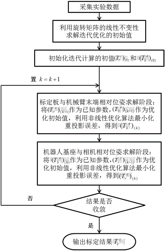
[0015] The invention discloses a method for calibrating the relative pose of a camera and a robot based on pixel space optimization. figure 1 Schematic diagram of the calibration method for the relative pose of the camera and the robot based on pixel space optimization. The specific steps are as follows:

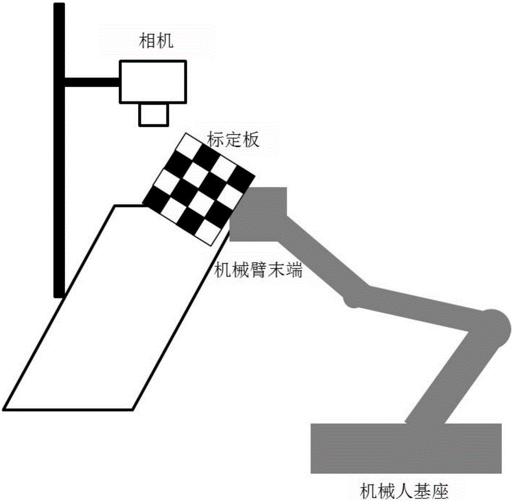
[0016] (1) Fix the calibration board at the end of the robot to control the movement of the robot so that when the movement stops, the calibration board is in the camera's field of view;

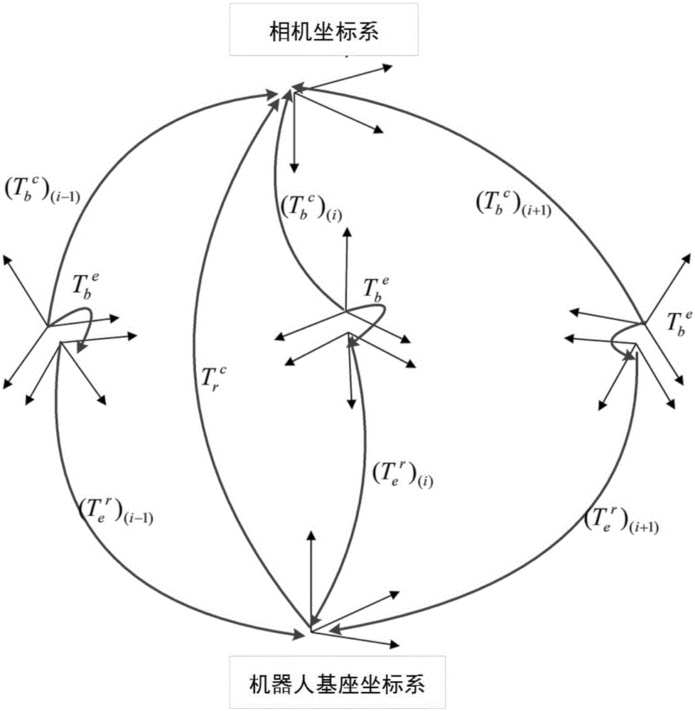
[0017] (2) When the movement stops, record the conversion relationship T from the robot end coordinate system to the base coordinate system e r , The image is collected to obtain the coordinates of the checkerboard corner points on the calibration board {(u 1 ,v 1 ),(u 2 ,v 2 ),...,(u m ,v m )}, calculate the conversion relationship T from the calibration board coordinate system to the camera coordinate system b c ;

[0018] (3) Control the robot to move n times to obtain the state data when n+1 m...


PUM


Abstract

The invention discloses a camera and robot relative pose calibration method based on pixel space optimization. According to the method, a calibration board carried at the tail end of a robot is adopted for moving inside the range of the view of a fixed camera, and space motion constraint information of the calibration board is utilized for calibration to obtain the optimal relative pose relation between the camera and a robot base. Firstly, linear invariance of a rotating matrix is utilized for solving a homogeneous transformation matrix to obtain a preliminary calibration result; then, the preliminary calibration result is used as an initial optimization value for optimization of pixel space, so that a reprojection error is made to the minimum. According to the camera and robot relative pose calibration method, the iterative optimization algorithm is adopted, no precision external measurement equipment is needed, model constraints of the image pixel space are utilized, the effective optimization initial value obtaining method is combined, the calibration result with the higher precision is obtained, and the requirement of a visual servo robot for completing positioning and grabbing working in industrial application can be met.

Description

Technical field [0001] The invention belongs to the field of advanced manufacturing and automation. Specifically, it is a method for calibrating the relative pose of a camera and a robot based on pixel space optimization. Background technique [0002] With the development of industrial robots, robot / manipulator operations based on visual servoing have been applied in more and more scenarios, which is currently the core issue of "machine substitution" and industrial transformation. Industrial robots with vision systems can interact with the environment more flexibly and intelligently, replacing humans to complete more tasks, and free workers from repetitive tasks on the assembly line. The accuracy of the visual sensor and the robot's spatial pose calibration is the key to ensuring the normal operation of the hand-eye system. The calibration accuracy determines the accuracy of the positioning and grasping of the visual servo robot. [0003] The problem of solving the relative positi...

Claims


Application Information

Patent Timeline
IPC IPC(8): B25J9/16
CPCB25J9/1605
Inventor 章逸丰程玉立熊蓉
Owner ZHEJIANG UNIV
Learn More