A vacuum tube high-speed train driven by electromagnetic force and inertial force and magnetically balanced with single track and single wheel

A high-speed train, magnetic balance technology, applied in electric vehicles, motor vehicles, electric traction, etc., can solve problems such as electromagnetic radiation pollution, and achieve the effect of low operating cost and low construction cost

Active Publication Date: 2021-06-01
高阳
View PDF9 Cites 0 Cited by
  • Summary
  • Abstract
  • Description
  • Claims
  • Application Information

AI Technical Summary

Problems solved by technology

Although the high-speed rail has been increased to an ultra-high speed of 300 kilometers per hour, and the speed of the maglev train has been increased to nearly 500 kilometers per hour, the trains are always subjected to air resistance and resonance resonance that are several times overloaded during high-speed operation. In addition, in the event of heavy rain, heavy snow, and typhoon, the weather is even more severe. Although the maglev train has no contact friction, no negative forces such as wheel-rail resonance, but the maglev train must first use a strong current to induce super strong The magnetic field of the same polarity suspends hundreds of tons of trains with a strong resistance force of the same polarity. This force is divided into about one ton for each passenger. At the same time, it will also generate strong electromagnetic radiation, which is harmful to the passengers in the car and the maglev line. Residents near both sides are suffering from electromagnetic radiation pollution, which is also the biggest objection to the maglev train at the application stage

Method used


Image

  • A vacuum tube high-speed train driven by electromagnetic force and inertial force and magnetically balanced with single track and single wheel
  • A vacuum tube high-speed train driven by electromagnetic force and inertial force and magnetically balanced with single track and single wheel
  • A vacuum tube high-speed train driven by electromagnetic force and inertial force and magnetically balanced with single track and single wheel

Examples


Embodiment Construction

[0020] In order to better clarify the purpose of the present invention, bring out the innovative advantages and beneficial effects of its inventive technology, and make the content of the present invention more concise and easy to read, it will be continued in detail in conjunction with specific embodiments of the present invention:

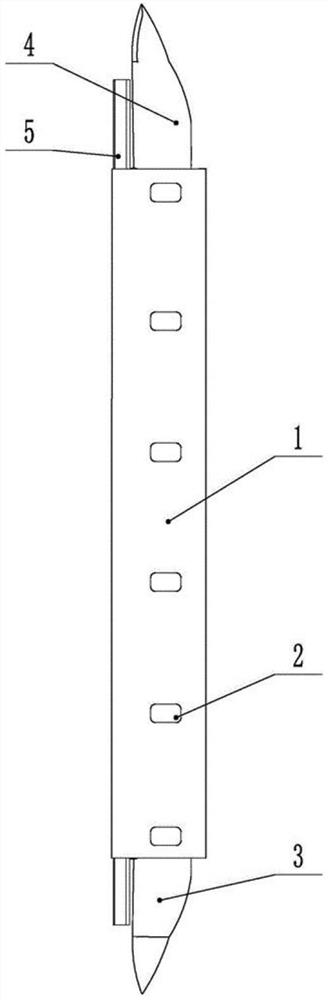
[0021] As shown in 1, it is a linear electromagnetic induction force traction and a high-speed inertial power train indicated by the schematic diagram of an embodiment of the present invention, a schematic diagram of the orientation from the vacuum pipeline in the station to the hairline. It comprises a vacuum pipeline line 1, a closed door 2 for passengers going up and down on the vacuum pipeline line in the station, a locomotive 4, a tailgate 3 of an up train and a single load-bearing rail 5 for supporting train operation in the vacuum pipeline line.

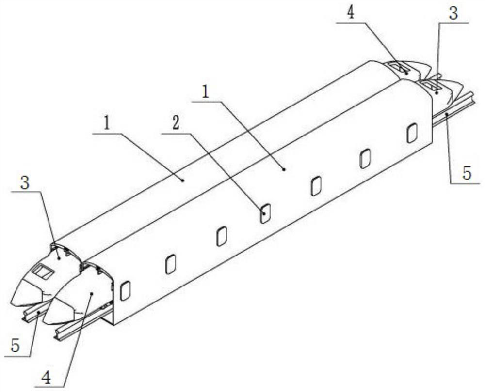
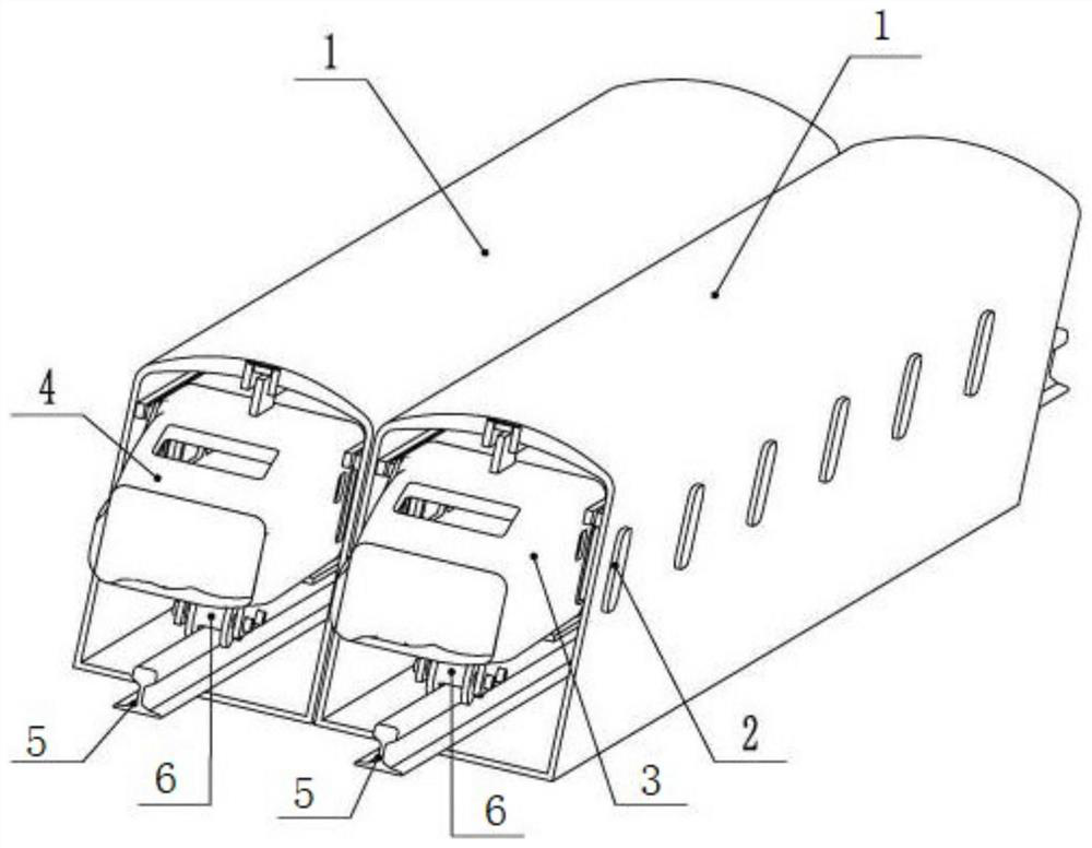
[0022] like figure 2 Shown, is the schematic diagram that two trains going up and down the v...


PUM


Abstract

A new type of non-resistance vacuum tube transportation method, multiple vacuum pipelines are arranged side by side in the vacuum tube station area line of the originating station, intermediate station and terminal station, and the main line of the up and down vacuum pipelines. It is composed of a linear electromagnetic induction force drive area and an inertial power area. It is used to connect the entire single-track single-wheel high-speed train line with vacuum pipelines. The two ends of the entrance and exit of each station are connected to the passage of the up and down trains or the entry and exit of the arrival and departure lines and the shunting operations in the station area through the individual track switches. , at the lower end of the center of the quarter of the length of the front and rear carriages of each carriage, a load-bearing single wheel is fixed, and a strong magnetic block is embedded in the upper end. There is no contact magnetic force balance during the running of the wheel train. The steel plate inside the vacuum tube is welded to evacuate, and the outside is protected by reinforced concrete. There is a telescopic transition door between each carriage door and the vacuum tube platform.

Description

technical field [0001] The invention discloses a vacuum tube high-speed train driven by electromagnetic force and inertial force and magnetically balanced on a single track and single wheel, belonging to the technical field of linear electromagnetic induction magnetic drive motors and a new type of rail transit technology for vacuum tubes with aerodynamics and no air resistance field. Background technique [0002] The meaning of rail transit is relatively broad. It includes railway trains, subways, light rails, intercity railways, electric traction, maglev trains and other rail transits. For more than 100 years, it has set a solid foundation for the production, life, economic development and civilization progress of human society. A lot of credit has been paid. [0003] In the 21st century, human society is developing towards high technology, intelligence, automation, high energy saving, high time saving, high environmental protection and high safety. Although the high-spe...

Claims


Application Information

Patent Timeline
Patent Type & Authority Patents(China)
IPC IPC(8): B61B13/06B60L13/04
Inventor 高士炳高阳
Owner 高阳
Why Eureka
Try Eureka