
Automatic pipe laying machine

A pipe-arranging machine and automatic technology, applied in the direction of conveyor objects, transportation and packaging, etc., can solve the problems of high error rate, high product loss rate, high labor intensity, and high labor cost, so as to reduce labor costs, improve work efficiency, and operate easy effect

Active Publication Date: 2015-11-04
HEBEI ANTAI PLASTIC PACKAGING PROD LTD
View PDF8 Cites 12 Cited by
  • Summary
  • Abstract
  • Description
  • Claims
  • Application Information

AI Technical Summary

Problems solved by technology

At present, the printing, capping and sealing of most manufacturers are all done manually, which has low work efficiency, high error rate and high product loss rate, and high labor cost in the factory.
Moreover, the monotonous and repetitive work makes the labor intensity of the worker's local body high

Method used


Image

  • Automatic pipe laying machine

Examples


Embodiment Construction

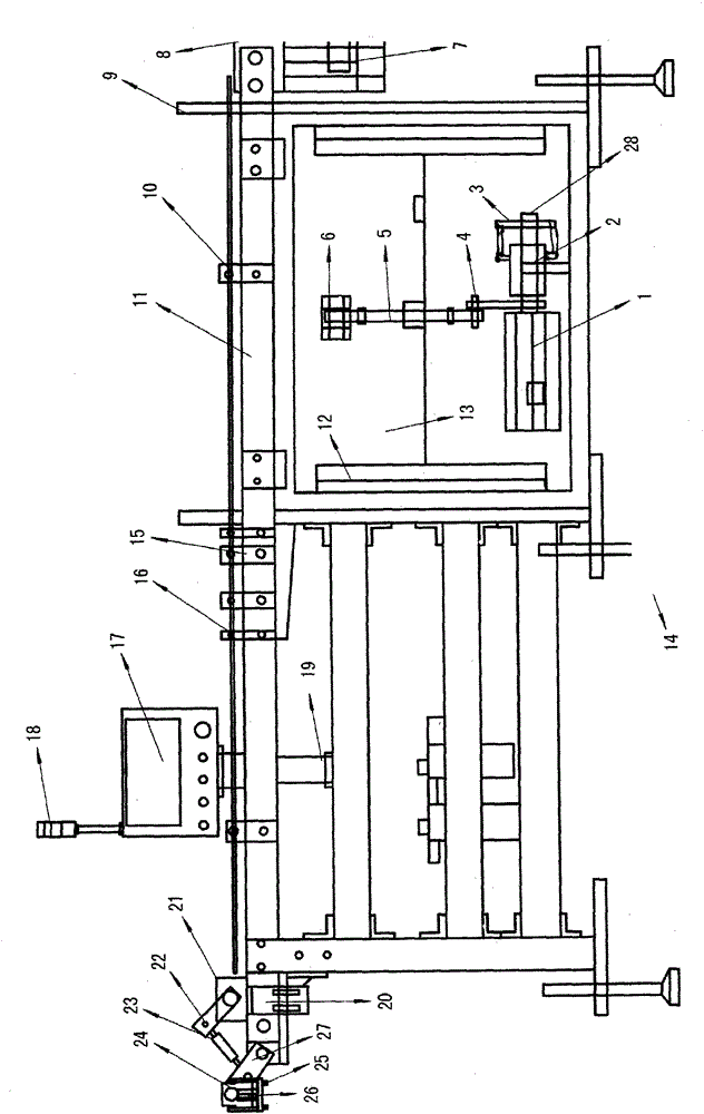
[0025] see figure 1 , The automatic pipe arrangement machine of the present invention is composed of four main structures: a hose jacking and feeding mechanism, a belt conveying line mechanism, a positive and negative head identification mechanism and a rotation and translation mechanism.

[0026] The hose jacking and feeding mechanism is located at the lower part of the front side of the pipe arrangement machine. The hose jacking and feeding mechanism includes a jacking motor 1 and a stepped feeding plate 13, and the connection between the jacking motor 1 and the stepped feeding plate 13 are connected by conduction facilities. Described conduction facility is made up of primary sprocket 2, driven sprocket 3, crank 4, connecting rod 5 and shaft support 6. The main sprocket 2 is installed on the shaft of the jacking motor 1, the main sprocket 2 drives the driven sprocket 3 through the chain, the connecting shaft 28 of the driven sprocket 3 is connected with the crank 4, and th...


PUM


Abstract

The invention discloses an automatic pipe laying machine. The automatic pipe laying machine consists of four main structures: a flexible pipe jacking and loading mechanism, a belt conveyor line mechanism, a front head and back head distinguishing mechanism and a rotary translation mechanism. According to the automatic pipe laying machine, manual operation is replaced, and a series of actions of automatic pipe trimming, automatic pipe feeding, automatic pipe turning and automatic pipe laying are realized. In this way, automatic continuous production can be realized, and a worker can operate and keep an eye on several pieces of equipment, so that the labor cost is remarkably reduced; and the automatic pipe laying machine has the characteristics of being wide in application range, simple and convenient to operate, high in efficiency and stable in operation.

Description

technical field [0001] The invention is an automatic pipe loading and pipe arrangement equipment for the matching production of offset printing, screw capping and tail sealing machines for rubber and injection-molded pipes. Background technique [0002] Hose products are widely used, such as medicine, travel supplies, cosmetics and so on. At present, most manufacturers do printing, capping, and sealing manually, which has low work efficiency, high error rate and high product loss rate, and high labor cost in the factory. Moreover, the monotonous and repetitive work makes the labor intensity of the worker's local body great. Contents of the invention [0003] In order to reduce the labor intensity of workers, improve work efficiency, and reduce the labor cost of factories, the present invention proposes an automatic pipe arrangement machine. [0004] The purpose of the present invention can be achieved through the following technical solutions: [0005] An automatic pi...

Claims


Application Information

Patent Timeline
Patent Type & Authority Applications(China)
IPC IPC(8): B65G47/24B65G47/26B65G47/91
Inventor 王大雨
Owner HEBEI ANTAI PLASTIC PACKAGING PROD LTD
Learn More