Deep and thick sand layer covered karst cave grouting system device and construction method

A technology of grouting system and construction method, which is applied in the direction of infrastructure engineering and construction, and can solve the problems of insufficient grouting, excessive grouting, personnel and property losses, etc., so as to avoid excessive grouting, increase the difficulty of forming grooves, and avoid sand and gravel missing effects

Inactive Publication Date: 2015-11-04
CHINA RAILWAY NO 5 ENG GRP +1
View PDF9 Cites 4 Cited by
  • Summary
  • Abstract
  • Description
  • Claims
  • Application Information

AI Technical Summary

Problems solved by technology

However, under the geological conditions where the karst limestone is directly covered with a deep sand layer, the sand layer and the karst cave can be connected after the hole is formed using this method. During the construction process, a series of construction parameters and indicators such as slurry feeding, return slurry, and pressure cannot be monitored to determine whether the final slurry standard is met, and it is impossible to determine whether the karst cave has been effectively filled, and karst collapse is prone to occur, resulting in personnel and property losses , and even cause great social impact
[0003] Therefore, in order to avoid the above problems, it is necessary to optimize the grouting system and construction technology on the basis of traditional construction, and provide a karst grouting system and construction method under deep sand coverage. This method not only avoids the loss of sand and gravel, At the same time, it solves the problems of insufficient and excessive grouting, and eliminates the risks of traditional techniques in this stratum.

Method used


Image

  • Deep and thick sand layer covered karst cave grouting system device and construction method
  • Deep and thick sand layer covered karst cave grouting system device and construction method

Examples


Embodiment Construction

[0012] The present invention will be further described below in conjunction with the accompanying drawings.

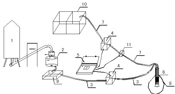
[0013] The grouting system equipment of the present invention is connected as figure 1 As shown, the cement tank 1, the grouting system 2 and the grouting machine 9 are connected through the grout inlet pipeline 3, and the mud recovery system is connected through the grout return pipeline 7; the grouting system includes a grouting recorder 5 and a grout stopper 6, wherein the grouting The recorder 5 is respectively connected to the flowmeter 4 and the pressure gauge 11, and the grout stopper 6 is placed on the roof of the cave 8, and the grout stopper 6 contains a grouting needle.

[0014] The flow meters 4 are respectively arranged on the grouting pipeline and the grouting pipeline.

[0015] The pressure gauge 11 is arranged on the slurry return pipeline.

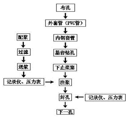
[0016] The karst grouting construction method under the deep sand layer coverage of the present invention, suc...


PUM


Abstract

The invention discloses a deep and thick sand layer covered karst cave grouting system device and grouting construction method. According to the system device, a cement tank (1), a slurrymaking system (2) and a grouting machine (9) are connected through slurry inlet pipelines (3), and are connected with a slurry recovery system through slurry return pipelines (7); a grouting system comprises a grouting recorder (5) and a slurry stop plug (6), the grouting recorder (5) is connected with flowmeters (4) and a pressure meter (11), the slurry stop plug (6) is placed on a top plate of a karst cave (8), and a grouting needle pipe is arranged in the slurry stop plug (6). The grouting construction method comprises the steps that 1, the cement tank, the slurrymaking system and the slurry recovery system are mounted; 2, drilling construction is carried out on an outer sleeve pipe till the outer sleeve pipe is close to a bed rock face as much as possible; 3, an inner steel sleeve pipe drills into bed rock by at least 0.5 m; 4, the bed rock is drilled to design depth; 5, the grouting system is mounted; and 6, cement slurry is pressed into the karst cave, grouting is stopped after the final slurry standard is met, and hole sealing is carried out.

Description

technical field [0001] The invention relates to a grouting construction equipment and a grouting construction method for karst caves under geological conditions of sand layers. Background technique [0002] At present, the grouting in the karst area usually adopts the construction technology of directly grouting the drill pipe or pulling out the drill pipe to inject grouting and sealing the hole with a disposable plastic pipe after the hole is formed. However, under the geological conditions where the karst limestone is directly covered with a deep sand layer, the sand layer and the karst cave can be connected after the hole is formed using this method. During the construction process, a series of construction parameters and indicators such as slurry feeding, return slurry, and pressure cannot be monitored to determine whether the final slurry standard is met, and it is impossible to determine whether the karst cave has been effectively filled, and karst collapse is prone to...

Claims


Application Information

Patent Timeline
IPC IPC(8): E02D15/02
Inventor 钟世华罗柳彭亮贺彬余嘉勤张爱品刘新明胡喜峰
Owner CHINA RAILWAY NO 5 ENG GRP
Why Eureka
Try Eureka