Jet AIP rotating hydrocarbon engine
A jet and engine technology, applied in the direction of machines/engines, mechanical equipment, etc., to achieve the effect of rich volume, superior power selection, and low price
- Summary
- Abstract
- Description
- Claims
- Application Information
AI Technical Summary
Problems solved by technology
Method used
Image

Examples
Embodiment 1
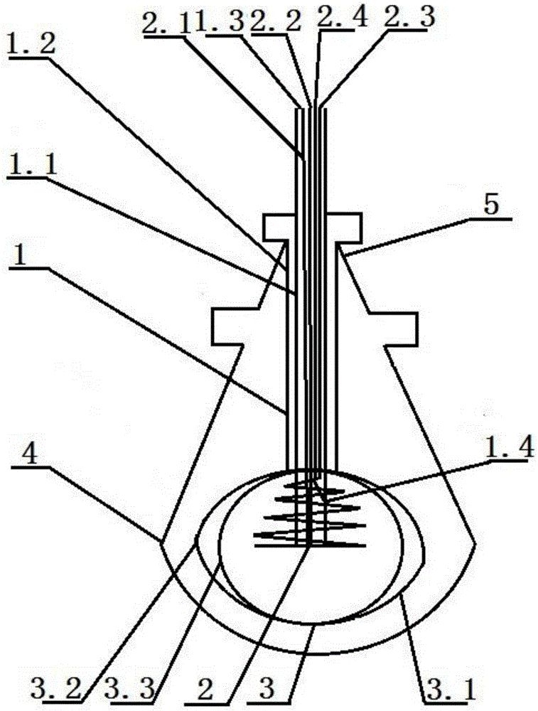
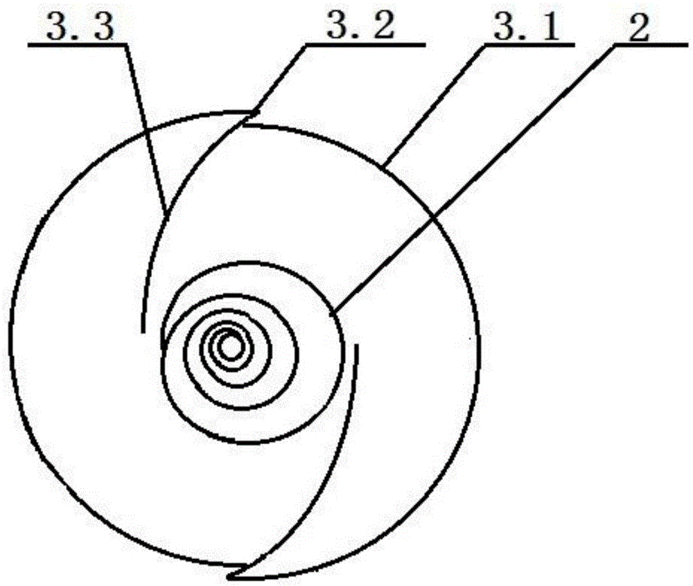
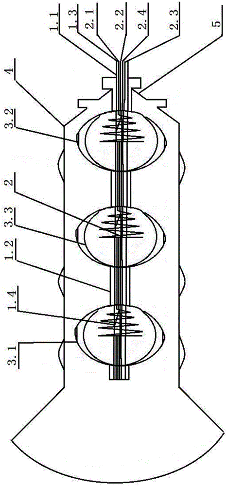
[0032] Embodiment 1: including a central shaft 1, an anode 2, a cathode 3, and a tornado cage 4. Among them, the central axis 1 is divided into the inner layer 1.1 that transports the cathode and anode energy bodies to enter and exit, and the outer layer 1.2 that wraps the inner layer 1.1 but does not contact the inner layer 1.1 and is connected to the output active force of the cathode 3. The layers are separated or retained by vacuum Air contact; the anode 2 is a hollow spiral ring, and the center point of the spiral ring is the junction of the hydrogen pipeline 2.1, the oxygen pipeline 2.2 entrance and the igniter. After being ignited by the igniter, the ignited hydrogen burns along the spiral all the way outward Go, and go back to the inner layer 1.1 of the central axis 1 of the anode at the end. The residual gas and combustion products are discharged from the outer port 1.3 of the central axis 1 through the residual gas pipeline 2.3. The outlet and inlet of the pipeline fo...
Embodiment 2
[0033] Embodiment 2: including a central shaft 1, an anode 2, a cathode 3, and a tornado cage 4. Among them, the central axis 1 is divided into the inner layer 1.1 that transports the cathode and anode energy bodies to enter and exit, and the outer layer 1.2 that wraps the inner layer 1.1 but does not contact the inner layer 1.1 and is connected to the output active force of the cathode 3. The layers are separated or retained by vacuum Air contact; the anode 2 is a hollow spiral ring, and the center point of the spiral ring is the junction of the hydrogen pipeline 2.1, the oxygen pipeline 2.2 entrance and the igniter. After being ignited by the igniter, the ignited hydrogen burns along the spiral all the way outward Go, and go back to the inner layer 1.1 of the central axis 1 of the anode at the end. The residual gas and combustion products are discharged from the outer port 1.3 of the central axis 1 through the residual gas pipeline 2.3. The outlet and inlet of the pipeline fo...
Embodiment 3
[0035] Embodiment 3: a jet-type AIP rotary hydrocarbon engine, characterized in that it includes a central axis 1, an anode 2, a cathode 3, and a tornado cage 4, wherein the central axis 1 is divided into an inner layer 1.1 and a package for transporting the energy body of the cathode and anode. The inner layer 1.1 does not contact the inner layer 1.1 and is connected to the outer layer 1.2 of the output active force of the cathode 3, and the layers are separated by vacuum or kept in contact with air; the anode 2 is a hollow spiral ring, and the center point of the spiral ring is The inlet of the hydrogen pipeline 2.1, the oxygen pipeline 2.2 and the junction of the igniter, after being ignited by the igniter, the ignited hydrogen burns along the spiral all the way outwards, and then wraps back to the inner layer 1.1 of the anode central axis 1 at the end , the residual gas and combustion products are discharged from the outer port 1.3 of the central axis 1 through the residual...
PUM
 Abstract
Description
Claims
Application Information
 - Generate Ideas
- Intellectual Property
- Life Sciences
- Materials
- Tech Scout
- Unparalleled Data Quality
- Higher Quality Content
- 60% Fewer Hallucinations
Browse by: Latest US Patents, China's latest patents, Technical Efficacy Thesaurus, Application Domain, Technology Topic, Popular Technical Reports.
© 2025 PatSnap. All rights reserved.Legal|Privacy policy|Modern Slavery Act Transparency Statement|Sitemap|About US| Contact US: help@patsnap.com