A combined denitrification device and method for a layer-fired boiler

A denitrification and boiler technology, applied in the field of pollutant emission control of coal-fired bed-fired boilers, can solve the problems of high natural gas prices, increased operating costs, poor denitrification effects, etc., and achieve the effects of energy saving, thermal efficiency improvement and emission reduction

Active Publication Date: 2017-11-10
HARBIN INST OF TECH
View PDF2 Cites 0 Cited by
  • Summary
  • Abstract
  • Description
  • Claims
  • Application Information

AI Technical Summary

Problems solved by technology

This method uses natural gas as the reburning gas. The price of natural gas is very high, which greatly increases the operating cost and is difficult to implement in practical applications.
(2) In-furnace SNCR denitrification technology, that is, spraying urea in the furnace to react with the generated NOx to form N 2 , to reduce NOx emissions, but due to the large section of the furnace, it is difficult for the urea sprayed into the furnace to mix evenly with the flue gas on the entire section of the furnace, resulting in poor denitration effect, and the denitration rate is generally only about 40%.

Method used


Image

  • A combined denitrification device and method for a layer-fired boiler
  • A combined denitrification device and method for a layer-fired boiler
  • A combined denitrification device and method for a layer-fired boiler

Examples


specific Embodiment approach 1

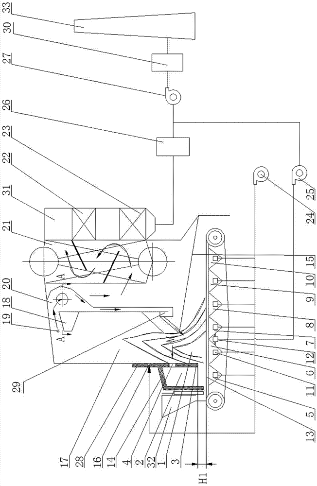
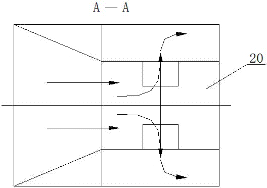
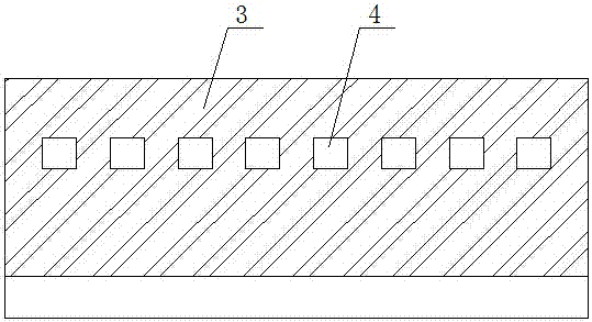
[0025] Specific implementation mode one: as Figure 1~Figure 4 As shown, a combined denitrification device for a layer-fired boiler includes a gasification chamber 2, a furnace partition wall 3, a flue gas channel 12, a fire grate 13, a furnace front arch 14, a furnace 17, a nozzle 19, and a horizontal cyclone with an acceleration section Separator 20, convection pipe 21, economizer 22, air preheater 23, blower 24, recirculation fan 25, dust collector 26, induced draft fan 27, return valve 29 and six air chambers; the six The air chambers are the gasification air chamber 5, the first air chamber 6, the second air chamber 7, the third air chamber 8, the fourth air chamber 9 and the fifth air chamber 10;

[0026]The lower front part of the furnace 17 is provided with a gasification chamber 2. The gasification chamber 2 is surrounded by a furnace front arch 14, a furnace partition wall 3 and two side walls of the furnace chamber. The furnace partition wall 3 is provided with a pl...

specific Embodiment approach 2

[0028] Specific implementation mode two: as figure 1 and Figure 4 As shown, in the combined denitrification device for the floor-fired boiler described in Embodiment 1, the grate 13 is a chain grate or a reciprocating grate, and the distance H1 between the lower surface of the furnace partition wall 3 and the upper surface of the chain grate is =450~550mm (preferably 500mm), the distance between the vertical extension surface of the rear side of the furnace partition wall 3 and the intersection line of the upper surface of the reciprocating fire grate to the lower surface of the furnace partition wall 3 H2=450~550mm ( 500mm is preferred). Such setting, on the one hand, can prevent the downward diffusion of gas, and on the other hand, the heat generated by the gasification chamber 2 is isolated from the outside, which is used for better coal gasification. In addition, it is also convenient for maintenance.

specific Embodiment approach 3

[0029] Specific implementation mode three: as figure 1 and Figure 4 As shown, in the combined denitrification device of the floor-fired boiler described in Embodiment 1, the outlet of the furnace 17 is located below the horizontal cyclone separator 20 with an acceleration section, and a flame angle 18 is provided. The effect is: on the one hand, the furnace 17 has a good flame filling degree, and strengthens the radiation heat transfer; on the other hand, it forms the acceleration section of the horizontal cyclone separator 2, ensuring that the separation efficiency of the horizontal cyclone separator 2 is greater than 95%, and at the same time, the urea and Good mixing of the flue gas is very beneficial.


PUM

PropertyMeasurementUnit
denitrification rateaaaaaaaaaa

Abstract

The invention belongs to the field of coal layer combustion boiler pollutant discharge control and discloses a layer combustion boiler combination denitration device and method. The invention aims to enable NOx discharged by layer combustion boilers to reach the standard. A vaporizing chamber is arranged below the front arch in a hearth, and the partition of the hearth is provided with a gas outlet. A vaporization air chamber, a first air chamber, a second air chamber, a third air chamber, a fourth air chamber and a fifth air chamber are sequentially formed below a fire grate from front to back. A secondary air port is formed in the part, above the front arch, of the front wall of the hearth. The outlet of the hearth is communicated with the inlet of a horizontal type cyclone separator with an acceleration section, and the bottom of the horizontal type cyclone separator with the acceleration section is communicated with a main combustion zone of the lower part of the hearth through a return valve. The horizontal type cyclone separator with the acceleration section is sequentially communicated with a convection calandria, an economizer and an air pre-heating device, the air pre-heating device is communicated with a dust remover, the dust remover is communicated with a recycling fan and a draught fan, and the recycling fan is communicated with a smoke channel. An air supply fan is communicated with the vaporization air chamber, the first air chamber, the second air chamber, the third air chamber, the fourth air chamber, the fifth air chamber and the secondary air port. The layer combustion boiler combination denitration device and method are used for layer combustion boiler combination denitration.

Description

technical field [0001] The invention relates to the control of NO by layer combustion furnace x The device and method for discharging belong to the field of pollutant emission control of coal-fired seam-fired boilers. Background technique [0002] Layer-burning furnaces are often used in concentrated urban residential areas, and most of them emit low-altitude emissions, which makes industrial boilers particularly pollute the surrounding environment, especially urban environments, while NO x Occupies a large share of pollutants, so it is economically effective to reduce the NO of the layer combustion furnace x Emissions play a very important role in reducing air pollution. [0003] At present, the NOx emission concentration of floor-fired boilers cannot meet the emission standards of GB13271-2014, and the simple SNCR is also difficult to meet the standards. Although the use of SCR at the tail can meet the standards, the investment and operation costs are high, and users are...

Claims


Application Information

Patent Timeline
Patent Type & Authority Patents(China)
IPC IPC(8): F23B90/06F23J15/02F23J15/06F23L7/00F23L15/00B01D53/78B01D53/56B01D45/16
CPCY02E20/34
Inventor 别如山范军万显君宋兴飞纪晓瑜陈佩李鹏坤房点顾文波
Owner HARBIN INST OF TECH
Why Eureka
Try Eureka