Servo system friction compensation method based on time Coulomb friction model

A technology of friction compensation and friction model, which is applied in general control systems, control/regulation systems, simulators, etc., can solve the problems of increasing the complexity of algorithms and the amount of calculations, and achieve the reduction of data processing, simple methods, and avoidance of control algorithms and the effect of the calculation of the friction parameter

Inactive Publication Date: 2015-11-04
HARBIN INST OF TECH
View PDF8 Cites 8 Cited by
  • Summary
  • Abstract
  • Description
  • Claims
  • Application Information

AI Technical Summary

Problems solved by technology

Therefore, some adaptive friction compensation schemes have appeared, and online identification of model parameters has greatly increased the complexity of the algorithm and the amount of calculation.

Method used


Image

  • Servo system friction compensation method based on time Coulomb friction model
  • Servo system friction compensation method based on time Coulomb friction model
  • Servo system friction compensation method based on time Coulomb friction model

Examples


Embodiment 1

[0026] 1. Proposal of time Coulomb friction model

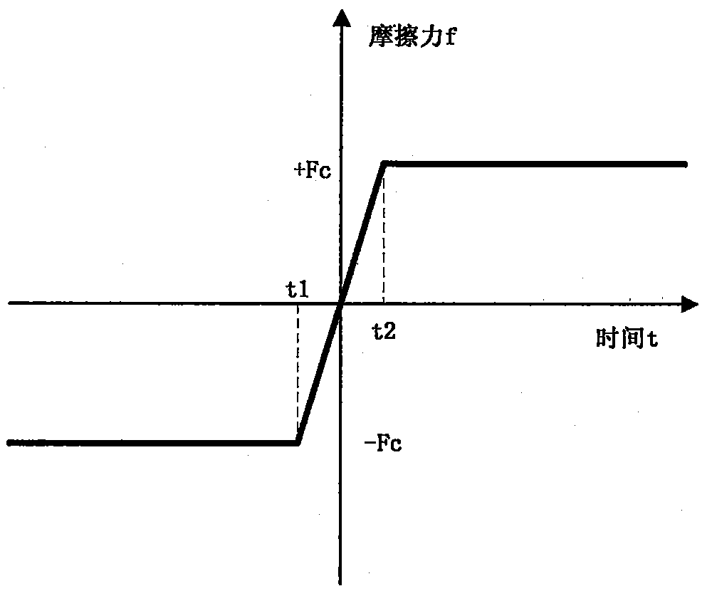
[0027] The time model of friction can be obtained from the speed model of friction. For the sake of simplicity, taking the Coulomb friction model as an example, a time Coulomb friction model is established to analyze the theoretical basis of this compensation method.

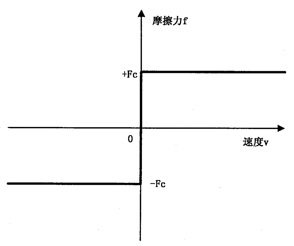
[0028] Such as figure 1 As shown, the Coulomb friction model is the simplest model, and its expression is: F=Fc*sgn(V). The Coulomb model believes that the magnitude of the friction force remains unchanged during the motion of the object. In fact, the friction force changes with the speed, so the deviation between the Coulomb friction model and the actual friction force is also the largest. Its advantage is that the expression is relatively simple, and it can reflect the change of friction force from -Fc to +Fc when the speed crosses zero, which is also the main interference factor that the servo system needs to overcome. Therefore, for the sake of simplicity...

Embodiment 2

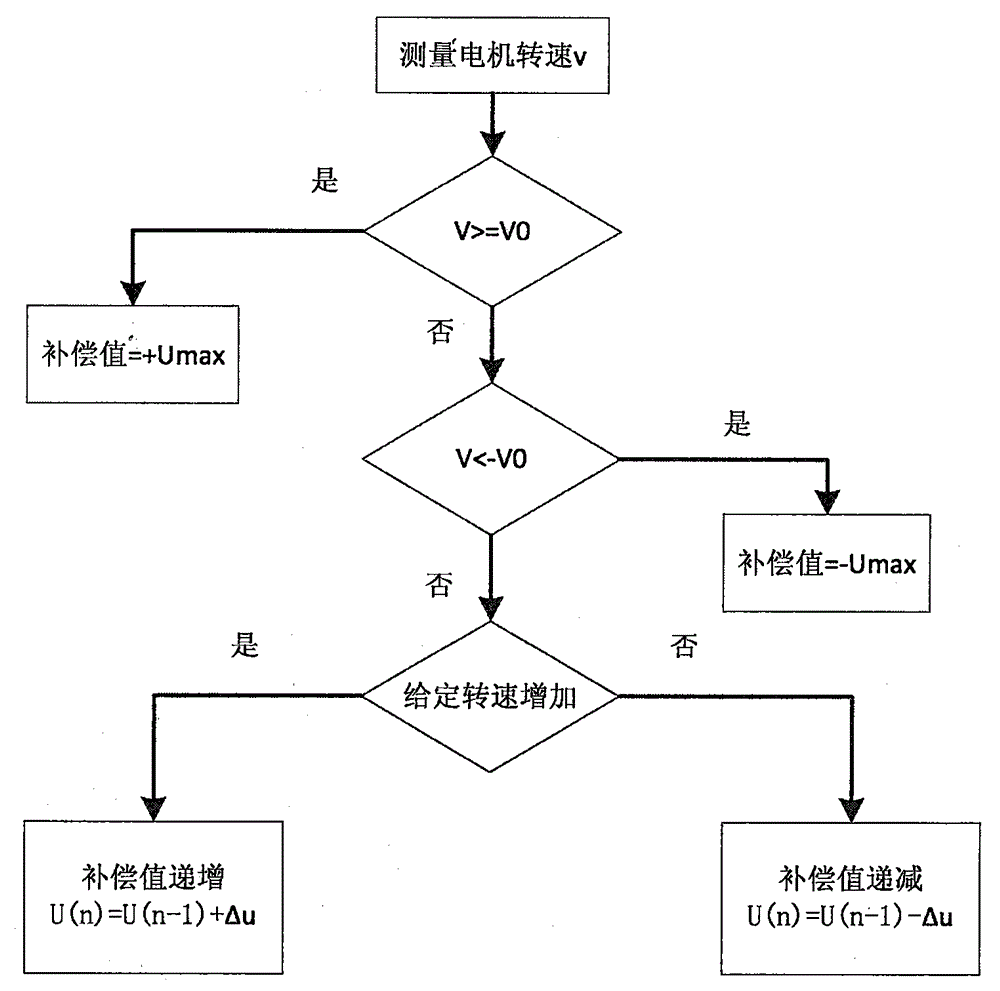
[0044] Such as Figure 5 Shown is the structural block diagram of the servo system, and the motor is affected by the friction torque during operation. Therefore, it is necessary to add a compensator in the output of the controller to counteract the influence of friction. according to image 3 As shown in the compensation flow chart, the input parameters required by the friction compensator include the given speed and the feedback speed, and the output of the friction compensator is added to the output of the PID controller as the total output of the controller.

[0045] In order to verify the effectiveness of the friction compensation method, a motor system with speed negative feedback is used for testing. The motor servo system includes TMS230F28335 DSP controller, PWM driver, motor, grating encoder, RS232 serial communication circuit and host computer, motor and drive parameters such as Image 6 shown.

[0046] Steps:

[0047] (1) Firstly, a time Coulomb friction model ne...


PUM


Abstract

The invention provides a servo system friction compensation method based on time Coulomb friction model, and the method comprises the steps of building a model of the frictional force that changes along with time; then outputting a compensation signal by a controller according to time; then determining the compensation value according to the measured motor rotating speed based on the given signal and offsetting the friction torque. The influence of the frictional force to the servo system can be effectively overcome; because the compensation value changes along with time continuously, abrupt change of the output signal from the controller is prevented; system robust stability is raised; and jitter phenomenon caused by output abrupt change of the controller is avoided.

Description

technical field [0001] The invention relates to a friction compensation method of a servo system based on a time Coulomb friction model. Background technique [0002] Friction is an important interference factor in the control process of the servo system. Especially at low speeds, the existence of friction may lead to dead zones and crawling phenomena at the zero speed crossing point. At present, the friction compensation methods mainly used are divided into two categories, one is the non-friction model method, which regards the change of friction force as a disturbance signal, and designs the controller from the perspective of improving system robustness and anti-interference ability, which can Effectively reduce the impact of friction, but cannot essentially compensate for the friction of the servo system. The other is the compensation method relying on the friction model, that is, to establish the model of the friction force changing with the speed first, such as Coulomb...

Claims


Application Information

Patent Timeline
Patent Type & Authority Applications(China)
IPC IPC(8): G05B19/404
CPCG05B19/404G05B2219/41154
Inventor 王毅柳佳男田琳
Owner HARBIN INST OF TECH
Why Eureka
Try Eureka