
Electric multi-leaf grating encoder closed-loop control system

A grating encoder, electric multi-leaf technology, applied in the direction of using feedback control, etc., can solve the problems that cannot meet the accuracy of electric multi-leaf grating control at the same time, CCD camera is not resistant to radiation, difficult adjustment and maintenance, etc., to achieve saving The effect of installation, maintenance and debugging time, reducing replacement and debugging time, and facilitating wiring

Active Publication Date: 2015-11-04
CHENGDU EBRIDGE TECH
View PDF10 Cites 6 Cited by
  • Summary
  • Abstract
  • Description
  • Claims
  • Application Information

AI Technical Summary

Problems solved by technology

The disadvantages are: CCD cameras are not resistant to radiation and need to be replaced frequently; and an optical system is required, which is difficult to adjust and maintain
The above two methods cannot meet the problem of accurate control of the blade position and low failure rate of the electric multi-leaf grating at the same time.

Method used


Image

  • Electric multi-leaf grating encoder closed-loop control system
  • Electric multi-leaf grating encoder closed-loop control system
  • Electric multi-leaf grating encoder closed-loop control system

Examples


Embodiment 1

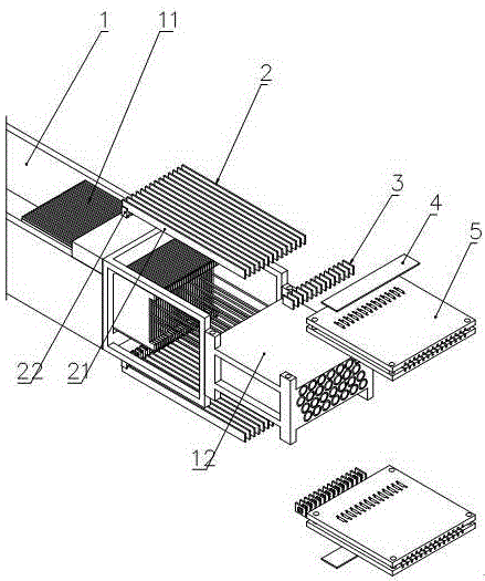
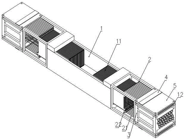
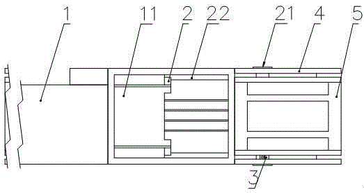
[0028] Such as Figure 1-5 As shown, the present invention includes an electric multi-leaf grating 1, and also includes a code bar 2, an integrated sensor 3, an integrated circuit board 4 and a code bar guide groove 5, and the connector 22 provided on the code bar 2 is connected to the electric multi-leaf grating 1 The blade 11 is fixed, and the code bar 2 is integrally arranged in the guide groove 54 of the code bar guide groove 5, and the code bar 2 moves linearly following the blade 11; the integrated circuit board 4 is fixed on a surface of the code bar guide groove 5; The integrated sensor 3 is composed of a circuit board 31 and a precision sensor 32 installed on the circuit board 31 , the circuit board 31 of the integrated sensor 3 is connected with the integrated circuit board 4 installed on one surface of the code bar guide groove 5 . The number of code bars and integrated sensors in this system corresponds to the number of blades. Each code bar is fixed with a single...

Embodiment 2

[0031] This embodiment is preferably as follows on the basis of Embodiment 1: in order to facilitate the free sliding of the code bar in the code bar guide groove, and to facilitate the blade to drive the code bar to perform linear motion in the code bar guide groove, the code bar guide groove 5 includes mutual The upper guide plate 51 and the lower guide plate 52 are parallel, and the upper guide plate 51 and the lower guide plate 52 are provided with fixing grooves 53 for installing the integrated sensor 3, and any fixing groove 53 is parallel to other fixing grooves 53.

Embodiment 3

[0033] The present embodiment is preferably as follows on the basis of the foregoing embodiments: on the facing surfaces of the upper guide plate 51 and the lower guide plate 52, guide grooves 54 for installing multiple bar code bars 2 are also arranged, and any guide groove 54 is mutually connected with other guide grooves 54. parallel. In this system, the guide groove of the code bar is designed with beryllium bronze material, and is matched with the code bar made of stainless steel. In the case of long-term movement, the wear on the guide groove of the code bar can be minimized as much as possible. The control system is more durable and effectively improves The use time of the system reduces the time for replacement and debugging.


PUM


Abstract

The invention discloses an electric multi-leaf grating encoder closed-loop control system, which comprises an electric multi-leaf grating and is characterized by further comprising a code bar, an integrated sensor, an integrated circuit board and a code bar guide slot, wherein a connector arranged on the code bar is fixed with a blade of the electric multi-leaf grating, the code bar is integrally arranged in a guide slot of the code bar guide slot, and the code bar carries out linear motion along with the blade; the integrated circuit board is fixed at one surface of the code bar guide slot; and the integrated sensor is composed a circuit board and a precision sensor installed on the circuit board, and the circuit board of the integrated sensor is connected with the integrated circuit board installed at one surface of the code bar guide slot. By adopting the structure disclosed by the invention, a closed-loop detection device applying a miniature high-precision encoder and the code bar is combined with the blade of the electric multi-leaf grating, accurate control for the position of the blade is realized through data processing of the encoder, the failure rate is reduced, and a purpose of accurate position control with high stability and good durability is achieved.

Description

technical field [0001] The invention relates to the field of medical device manufacturing control, in particular to a closed-loop control system of an electric multi-leaf grating encoder. Background technique [0002] Most of the motorized multi-leaf grating leaf displacement detection on the market now uses high-precision linear potentiometers or CCD camera systems. It adopts high-precision linear potentiometer, which has good linearity and precision. The disadvantage is that it is difficult to find faults due to too many wirings, and a high-precision linear potentiometer is required. Using the CCD camera system, the advantages are: MLC position real-time display, not too much wiring, high spatial resolution and position linearity, etc. The disadvantages are: the CCD camera is not resistant to radiation and needs to be replaced frequently; and it needs an optical system, which is difficult to adjust and maintain. The above two methods cannot simultaneously satisfy the pr...

Claims


Application Information

Patent Timeline
IPC IPC(8): G05D3/12
Inventor 吕力
Owner CHENGDU EBRIDGE TECH
Learn More