Spinal cord micro-catheter stent fast to form and manufacturing method thereof
A technology for microcatheter and spinal cord, applied in the field of rapid prototyping spinal cord microcatheter stent and its preparation, can solve the problems of spatial structure gap, limited nerve function repair effect, etc., achieves high accuracy, promotes orderly directional growth, and high additional effect of value
- Summary
- Abstract
- Description
- Claims
- Application Information
AI Technical Summary
Problems solved by technology
Method used
Image
Examples
Embodiment 1
[0033] Embodiment 1 rapidly prototyping spinal cord microcatheter support
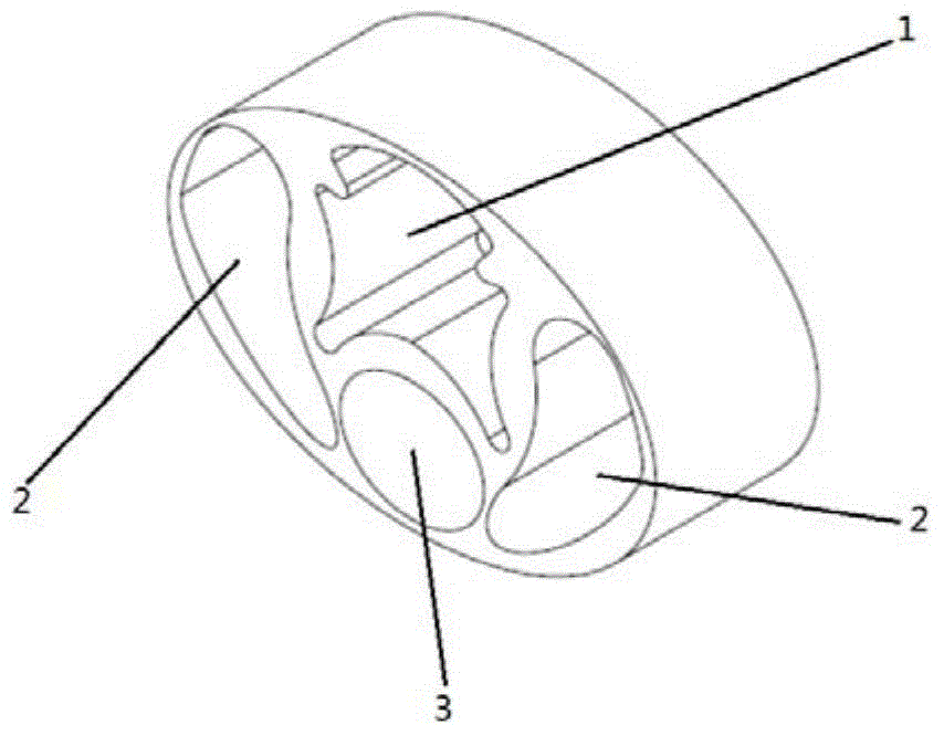
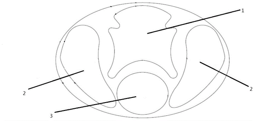
[0034] Such as figure 1 , 2 As shown, it includes an elliptical cylindrical microcatheter stent body, and the microcatheter stent body is provided with hollow areas for growing corticospinal tracts, thin tracts, wedge tracts and spinothalamic tracts; the hollow areas include the first support area 1, the second Stent region 2 and the third stent region 3; the center of the upper half of the microcatheter stent body is provided with the first stent region 1 for growing thin bundles and wedge bundles; , The second bracket area 2 of the spinothalamic tract; the third bracket area 3 is arranged below the first bracket area 1; the outer diameter of the spinal cord microcatheter bracket is 2.5-3.5 mm, and the wall thickness is 0.1-1.0 mm; the third bracket area 3 With a diameter of 200-400 μm, the third scaffold area is used for precision control.
[0035] The spinal cord microcatheter scaffold of the pre...
Embodiment 2
[0039] The preparation of embodiment two spinal cord microcatheter support
[0040] (1) Prepare a fresh spinal cord sample at the thoracic 10 level of the rat, and measure its main parameter data, such as diameter, transverse diameter, hardness, elastic modulus, and strength;
[0041] (2) According to the anatomical structure and measurement data of the rat spinal cord, comparative analysis was carried out to understand the diameter and course of the spinal corticospinal tract, spinothalamic tract, thin tract and wedge tract, design and optimize the 3D model of the spinal cord microcatheter scaffold, and conduct finite element analysis Analysis; import the 3D model of the spinal cord microcatheter into the 3D bioprinter computer for format conversion, data simulation and parameter optimization;
[0042] (3) Take silk protein as raw material, take silk, put silk raw material into 80-120 ℃ Na 2 CO 3 solution, boiled at high temperature for 30-60min, washed repeatedly with dist...
Embodiment 3
[0046] The preparation of embodiment three spinal cord microcatheter support
[0047] (1) According to the comparative analysis of the anatomical structure and measurement data of the spinal cord nerves in rats, understand the diameter and course of the spinal corticospinal tract, spinothalamic tract, thin tract and wedge tract, design and optimize the 3D model of the spinal cord microcatheter scaffold, and conduct finite element analysis Analysis; import the 3D model of the spinal cord microcatheter into the 3D bioprinter computer for format conversion, data simulation and parameter optimization. The diameter is 2.5-2.8mm and the transverse diameter is 2.2-2.5mm;
[0048] (2) Using silk protein and hydroxyapatite as raw materials, take silk, and put the silk raw material into 80-120°C Na 2 CO 3 solution, boiled at high temperature for 30-60min, washed repeatedly with distilled water; repeated boiling and washing 2-3 times, vacuum drying to complete degumming; 2 , ethanol, w...
PUM
| Property | Measurement | Unit |
|---|---|---|
| thickness | aaaaa | aaaaa |
| diameter | aaaaa | aaaaa |
Abstract
Description
Claims
Application Information
 - R&D
- Intellectual Property
- Life Sciences
- Materials
- Tech Scout
- Unparalleled Data Quality
- Higher Quality Content
- 60% Fewer Hallucinations
Browse by: Latest US Patents, China's latest patents, Technical Efficacy Thesaurus, Application Domain, Technology Topic, Popular Technical Reports.
© 2025 PatSnap. All rights reserved.Legal|Privacy policy|Modern Slavery Act Transparency Statement|Sitemap|About US| Contact US: help@patsnap.com


