Eureka AIR delivers breakthrough ideas for toughest innovation challenges, trusted by R&D personnel around the world.

Pressure-infiltration coating device and method applicable to porous ceramic matrix photocatalytic filler block

A technology of porous ceramics and coating devices, applied in chemical instruments and methods, physical/chemical process catalysts, chemical/physical processes, etc. Problems such as the inability of the precursor plating solution to penetrate into the pores of the core to achieve the effects of high coverage of the loaded film, simple structure, and improved penetration

Active Publication Date: 2015-11-11
HOHAI UNIV
View PDF4 Cites 0 Cited by
  • Summary
  • Abstract
  • Description
  • Claims
  • Application Information

AI Technical Summary

Problems solved by technology

However, due to the three-dimensional porous structure of porous ceramic materials, the precursor liquid can only be coated on the outer layer of the porous ceramic body by dipping or spraying, and the precursor liquid cannot penetrate into the pores inside the ceramic body, resulting in Nano-TiO can only be loaded on the outer layer of porous ceramics 2 thin film, but not inside, which greatly reduces the 2 The effective use area of ​​photocatalytic materials, especially for larger porous ceramic filler blocks, its nano-TiO 2 The loading area of ​​the film is lower, which also greatly hinders the porous ceramic-based nano-TiO 2 Promotion and use of photocatalytic materials
The present invention proposes a piezo-osmotic coating device and method suitable for porous ceramic-based photocatalytic filler blocks, which can effectively solve the problem that the precursor plating solution cannot penetrate into the core holes in the process of loading photocatalytic membranes on porous ceramics. and method can prepare porous ceramic photocatalytic materials with higher film coverage

Method used


Image

  • Pressure-infiltration coating device and method applicable to porous ceramic matrix photocatalytic filler block
  • Pressure-infiltration coating device and method applicable to porous ceramic matrix photocatalytic filler block
  • Pressure-infiltration coating device and method applicable to porous ceramic matrix photocatalytic filler block

Examples


Embodiment Construction

[0018] The technical solutions of the present invention will be further described in detail below in conjunction with the embodiments and the accompanying drawings, but the protection scope of the present invention is not limited to the embodiments.

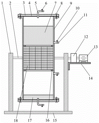
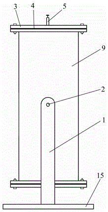
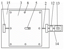
[0019] Such as Figure 1~Figure 4 As shown, a piezo-infiltration coating device suitable for porous ceramic-based photocatalytic packing block, its structure includes a reaction tank device, a rotating shaft 2, an air intake pipe 5, an exhaust pipe 11, a support frame 1, a base 15, a motor 13 and a reduction box 12; wherein the reaction tank body 9 in the reaction tank device is a cuboid hollow tank body, and end caps 3 are installed at both ends of the reaction tank body 9 to seal the tank body; Fixed on the support frame 1, the support frame 1 is fixed on the base 15, and the reaction tank device can be rotated on the base 15; the lining plate 16 is installed inside the reaction tank body 9, and the porous ceramic block 18 is f...


PUM


Abstract

The invention discloses a pressure-infiltration coating device and method applicable to a porous ceramic matrix photocatalytic filler block. The pressure-infiltration coating device is characterized by comprising a reaction tank body, a rotating shaft, an air inlet pipe, air outlet pipes, a support frame, a base, a motor and a reduction gearbox; the reaction tank body is a hollow cuboid; two end covers are mounted at the two ends of the reaction tank body, so as to seal the reaction tank body; the rotating shaft is fixed in the middles on two sides of the reaction tank body; the two ends of the rotating shaft is fixed on the support frame; two lining plates are mounted in the reaction tank body; the porous ceramic block is fixed between the lining plates; the air inlet pipe is mounted in the middle of one end cover; the tail end of the air inlet pipe is connected with an air inlet valve; the air outlet pipes are mounted on one side wall of the reaction tank body; the tail ends of the air outlet pipes are connected with air outlet valves; the motor and the reduction gearbox are fixed on a bracket on one side of the support frame, and connected with the rotating shaft; the motor can drive the reaction tank body to rotate around the rotating shaft. Through the adoption of the device and method, a porous ceramic matrix nanometer photocatalytic material is prepared, has the advantages that the coverage rate of an immobilized film is high and the combination is firm, and can be utilized for mass production.

Description

technical field [0001] The invention relates to a pressure infiltration coating device and method suitable for porous ceramic-based photocatalytic filler blocks, and belongs to the technical field of composite material forming. Background technique [0002] In recent years, with the continuous acceleration of the industrialization process, a large amount of waste water and waste gas have seriously affected human health and the living environment. Environmental pollution control has become one of the important problems facing and urgently to be solved in modern society. The methods currently being used such as chemical oxidation, physical adsorption, high-temperature incineration and microbial treatment have played a certain role in environmental protection and governance, but these methods have some shortcomings to varying degrees, such as low efficiency and inability to completely Control pollution, easily produce secondary pollution, high energy consumption and other issue...

Claims


Application Information

Patent Timeline
Patent Type & Authority Applications(China)
IPC IPC(8): B01J35/10C02F1/30
Inventor 王沛芳饶磊王超钱进侯俊敖燕辉
Owner HOHAI UNIV
Why Eureka
Eureka Blog
Learn More