Cutter box transmission device of numerical control double-cutter-head straight bevel gear milling machine

A straight-toothed bevel gear and transmission technology, which is applied in the direction of driving devices, manufacturing tools, metal processing machinery parts, etc., can solve the problems of increasing processing costs, machine tool adjustment, configuration time, low transmission accuracy and transmission efficiency, and affecting machine tool processing efficiency and other problems, to achieve the effect of simplified structure, reduced structure, convenient operation and adjustment

Inactive Publication Date: 2015-11-11
TIANJIN NO 1 MACHINE TOOL WORKS
View PDF8 Cites 0 Cited by
  • Summary
  • Abstract
  • Description
  • Claims
  • Application Information

AI Technical Summary

Problems solved by technology

The planetary mechanism and the clutch are used together to realize the tooth-splitting movement, and the gear ratio and the number of teeth of the gear pair to be processed are adjusted. In actual operation, not only the calculation is complicated, but additional manufacturing is required, which increases the processing cost and machine tool adjustment and configuration time. Therefore, it is not suitable for single-piece or small-batch gear processing
In addition, due to the use of two sets of cradle structures, the transmission chain of the transmission device is longer, and the transmission accuracy and transmission efficiency are low, which in turn affects the processing efficiency of the machine tool

Method used


Image

  • Cutter box transmission device of numerical control double-cutter-head straight bevel gear milling machine
  • Cutter box transmission device of numerical control double-cutter-head straight bevel gear milling machine
  • Cutter box transmission device of numerical control double-cutter-head straight bevel gear milling machine

Examples


Embodiment Construction

[0019] In order to further understand the invention content, characteristics and effects of the present invention, the following examples are given, and detailed descriptions are as follows in conjunction with the accompanying drawings:

[0020] It should be noted that, unless otherwise specified and limited, terms such as "first" and "second" do not represent sequential installation, nor do they represent the importance of the described components.

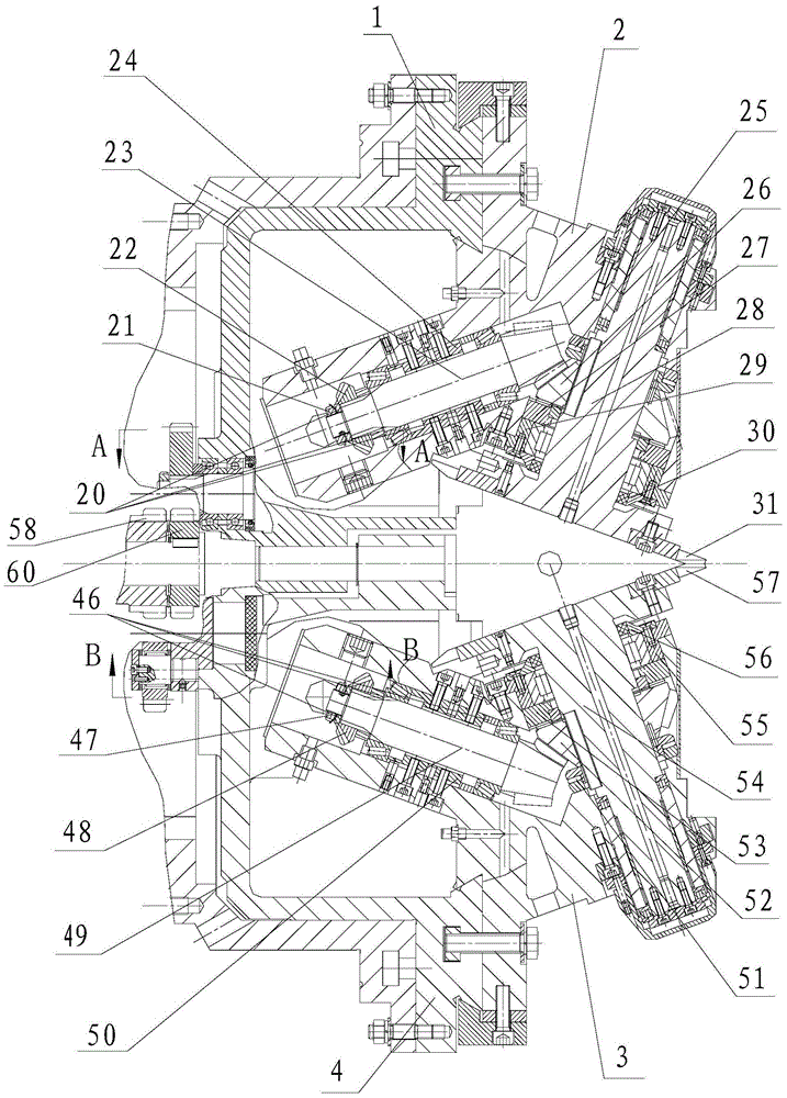
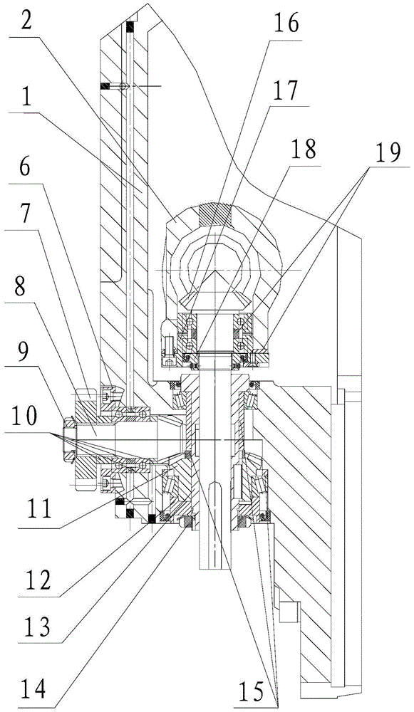
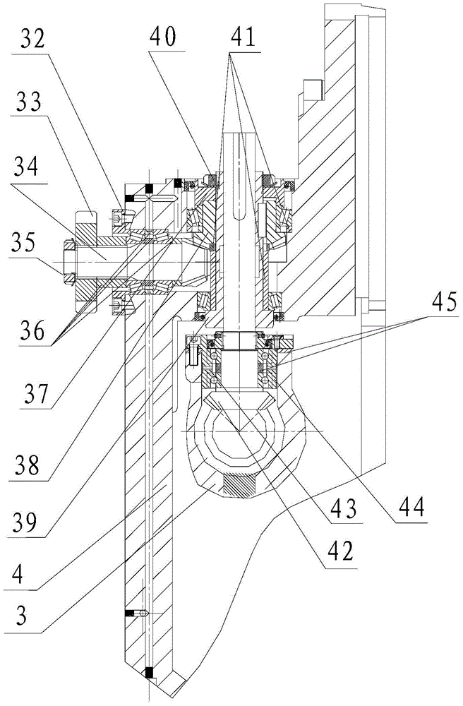
[0021] see Figure 1-Figure 4 , the tool box transmission device of the CNC double cutterhead straight bevel gear milling machine includes: the upper tool holder seat transmission mechanism, the lower tool holder seat transmission mechanism, the upper tool box transmission mechanism and the lower tool box transmission mechanism, the upper tool holder seat The transmission mechanism constitutes a transmission chain through the first spur gear 7 installed on the first bevel gear shaft 8 and the upper transmission intermediate wheel...


PUM


Abstract

The invention relates to a cutter box transmission device of a numerical control double-cutter-head straight bevel gear milling machine. The cutter box transmission device is characterized in that the cutter box transmission device comprises an upper cutter rest seat transmission mechanism, a lower cutter rest seat transmission mechanism, an upper cutter rest transmission mechanism and a lower cutter rest transmission mechanism; the upper cutter rest seat transmission mechanism and a cradle assembly inner transmission wheel A form a transmission chain through a first straight gear and an upper transmission intermediate wheel; the lower cutter rest seat transmission mechanism and a cradle assembly inner transmission wheel B form a transmission chain through a second straight gear and a pair of lower transmission intermediate wheels; the upper cutter rest transmission mechanism forms a transmission chain through a second bevel gear shaft, a second bevel gear, a third bevel gear shaft and a third bevel gear; and the lower cutter rest transmission mechanism forms a transmission chain through a fifth bevel gear shaft, a fourth bevel gear, a sixth bevel gear shaft and a sixth bevel gear. The cutter box transmission device has the beneficial effects that the machine tool structure and all the movement shaft transmission chains can be sufficiently simplified, the manufacturing cost can be reduced, and the gear cutting precision can be greatly improved; and batch gear machining can be achieved, and the production requirements for small and medium batches and multiple varieties can be met.

Description

technical field [0001] The invention belongs to the technical field of gear processing machine tools, in particular to a tool box transmission device of a numerically controlled double-cutter straight bevel gear milling machine. Background technique [0002] Straight bevel gear milling machines can be divided into horizontal single-station spur bevel gear milling machine and vertical double-station spur bevel gear milling machine according to their layout, vertical double-station spur bevel gear milling machine The gear machinist includes cutter head, cradle, workpiece head, cradle hydraulic slide table, cutter head hydraulic slide table, base, hydraulic cooling system and electric control system and other main components. In order to process the paired large and small gears in the gear pair, two sets of cradles and workpiece heads connected with the cradles are installed on the bed. The gear to be processed on the head revolves, and the worm gear pair of the workpiece head...

Claims


Application Information

Patent Timeline
Patent Type & Authority Applications(China)
IPC IPC(8): B23Q5/04B23F5/20
CPCB23Q5/04B23F5/205
Inventor 陈义召吴文仲刘艳岭李雪梅付维强曹阳
Owner TIANJIN NO 1 MACHINE TOOL WORKS
Why Eureka
Try Eureka