Laser marking device

A technology of laser and laser generator, which is applied in printing and other directions, can solve the problems of inconvenient changes in printing content, inability to meet diversified production needs, and inability to meet the requirements of processing accuracy.

Inactive Publication Date: 2015-11-11
江苏艺佳精密仪器制造有限公司
View PDF5 Cites 5 Cited by
  • Summary
  • Abstract
  • Description
  • Claims
  • Application Information

AI Technical Summary

Problems solved by technology

The effect of marking is to expose deep substances through the evaporation of surface substances, thereby engraving exquisite patterns, trademarks and characters; electrocorrosion mainly prints fixed trademarks, just like stamping, but it is inconvenient to change the printing content
The content that needs to be marked on the lens support frame mainly includes scale, product information, etc., and

Method used


Image

  • Laser marking device
  • Laser marking device

Examples


Embodiment Construction

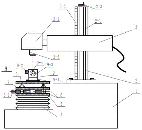
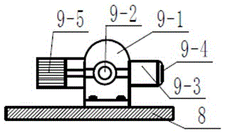
[0011] Depend on figure 1 , figure 2 Known, the structure diagram of the present invention is made up of main support 1, column 2, laser generator 3, telescopic plate 4, telescopic support plate 5, mobile support assembly 6, left and right sliding plate 7, front and rear sliding plate 8, tooling support assembly 9 , the column 2 is installed and fixed on the upper right side of the main bracket 1 by bolts, the laser generator 3 is installed on one side of the column 2, the telescopic plate 4 is fixed on the lower left side of the main bracket 1, and the telescopic support plate 5 is installed above the telescopic plate 4, The mobile support assembly 6 is arranged between the telescopic support plate 5 and the left and right sliding plates 7, the mobile support assembly 6 is arranged between the front and rear sliding plates 8 and the left and right sliding plates 7, the tooling support assembly 9 is installed above the front and rear sliding plates 8, and is in the Right bel...


PUM


Abstract

The invention discloses a laser marking device. The laser marking device is composed of a main support (1), a stand column (2), a laser generator (3), a telescopic plate (4), a telescopic supporting plate (5), a movable support assembly (6), a left and right sliding plate (7), a front and back sliding plate (8) and a tool support assembly (9). The stand column (2) is fixed to the upper right part of the main support (1) through a bolt. The laser generator (3) is installed on one side of the stand column (2). The laser generator (3) is installed on a sliding rail (2-1) of the stand column (2). A scale ruler (2-2) is arranged on one side of the stand column (2). The height of the laser generator (3) is adjusted through a rotating handle (2-3). The laser marking device is simple in structure; a tool head is replaced, so that the purpose of installing different lens parts is achieved; a driving motor drives the tool head to conduct rotary motion so that etching and marking can be conducted on a curved surface; and the purpose that the laser marking device has multiple functions is achieved.

Description

technical field [0001] The invention relates to the field of etching technology processing, in particular to a marking device used for etching a lens metal cover. Background technique [0002] Marking machine is mainly divided into three types: pneumatic, laser, and electric corrosion. Pneumatic: computer control, the printing needle makes high-frequency impact movement under the action of compressed air, so as to print a mark with a certain depth on the workpiece. Marking features: There is a greater depth; the laser marking machine uses a laser beam to permanently mark the surface of various substances. The effect of marking is to expose deep substances through the evaporation of surface substances, thereby engraving exquisite patterns, trademarks and characters; electrocorrosion mainly prints fixed trademarks, just like stamping, but it is inconvenient to change the printing content. The content that needs to be marked on the lens support frame mainly includes scale, pro...

Claims


Application Information

Patent Timeline
IPC IPC(8): B41J2/435
Inventor 罗立军徐洋
Owner 江苏艺佳精密仪器制造有限公司
Why Eureka
Try Eureka