Deposition furnace for the preparation of quartz glass ingots

A quartz glass and deposition furnace technology, applied in glass furnace equipment, glass manufacturing equipment, manufacturing tools, etc., can solve the problems of uneven structure, longitudinal distribution of quartz glass in layers, affecting the uniformity of longitudinal structure, etc., and achieve uniform distribution. , Improve the uniformity of structure and reduce the effect of temperature gradient

Active Publication Date: 2018-04-10
CHINA BUILDING MATERIALS ACAD
View PDF9 Cites 0 Cited by
  • Summary
  • Abstract
  • Description
  • Claims
  • Application Information

AI Technical Summary

Problems solved by technology

[0004] The temperature gradient on the deposition surface will cause a large difference in the structure of the quartz glass ingot from the center to the edge. For example, the hydroxyl content of the quartz glass gradually decreases along the center to the edge, which leads to uneven distribution of the refractive index and density of the quartz glass. , which in turn affects the structural uniformity of the deposition surface direction of the quartz glass
At the same time, the deposition mechanism of quartz glass ingots produced by this deposition furnace is formed by centrifugal force and gravity, which is forced to gradually diffuse from the center to the edge, that is, the entire deposition surface is in a normal distribution shape, resulting in the appearance of longitudinal distribution Layered phenomenon seriously affects the uniformity of its longitudinal structure
Therefore, the quartz glass ingots manufactured by the existing deposition furnaces have uneven structures, which in turn affect the one-dimensional and three-dimensional optical uniformity, stress and other properties of the quartz glass, and eventually damage the precision of aerospace, nuclear technology, precision instruments and other fields. Image quality of the optical system

Method used


Image

  • Deposition furnace for the preparation of quartz glass ingots
  • Deposition furnace for the preparation of quartz glass ingots
  • Deposition furnace for the preparation of quartz glass ingots

Examples


Embodiment Construction

[0028] The present invention will be described in further detail below in conjunction with specific examples, but not as a limitation of the present invention. In the following description, different "one embodiment" or "embodiment" do not necessarily refer to the same embodiment. Furthermore, the particular features, structures, or characteristics of one or more embodiments may be combined in any suitable manner.

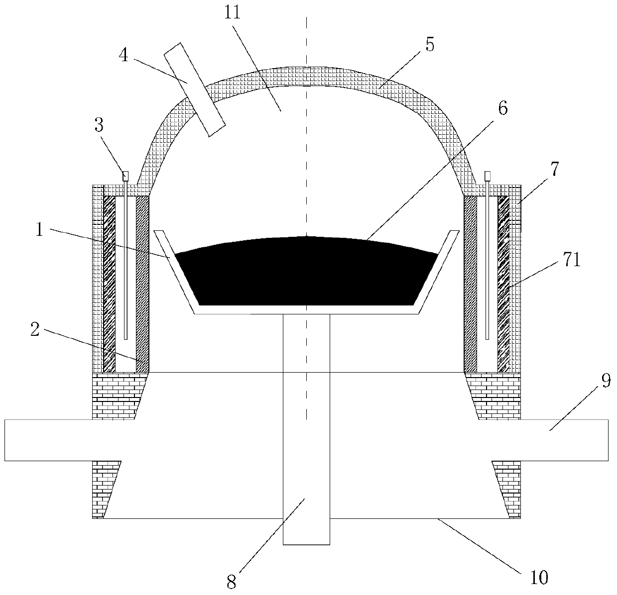
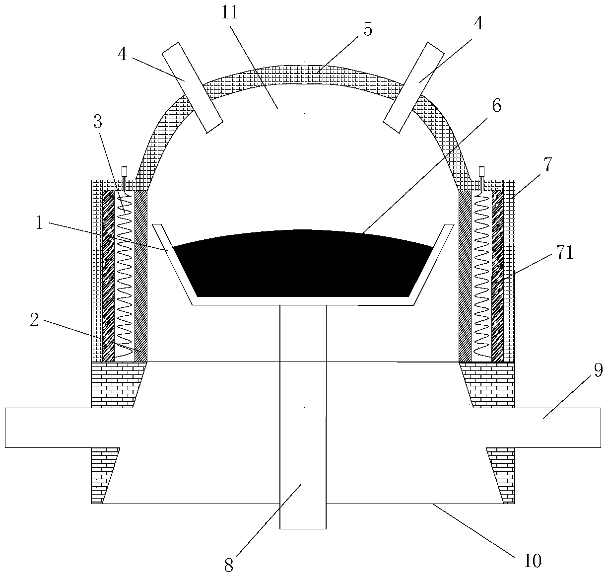
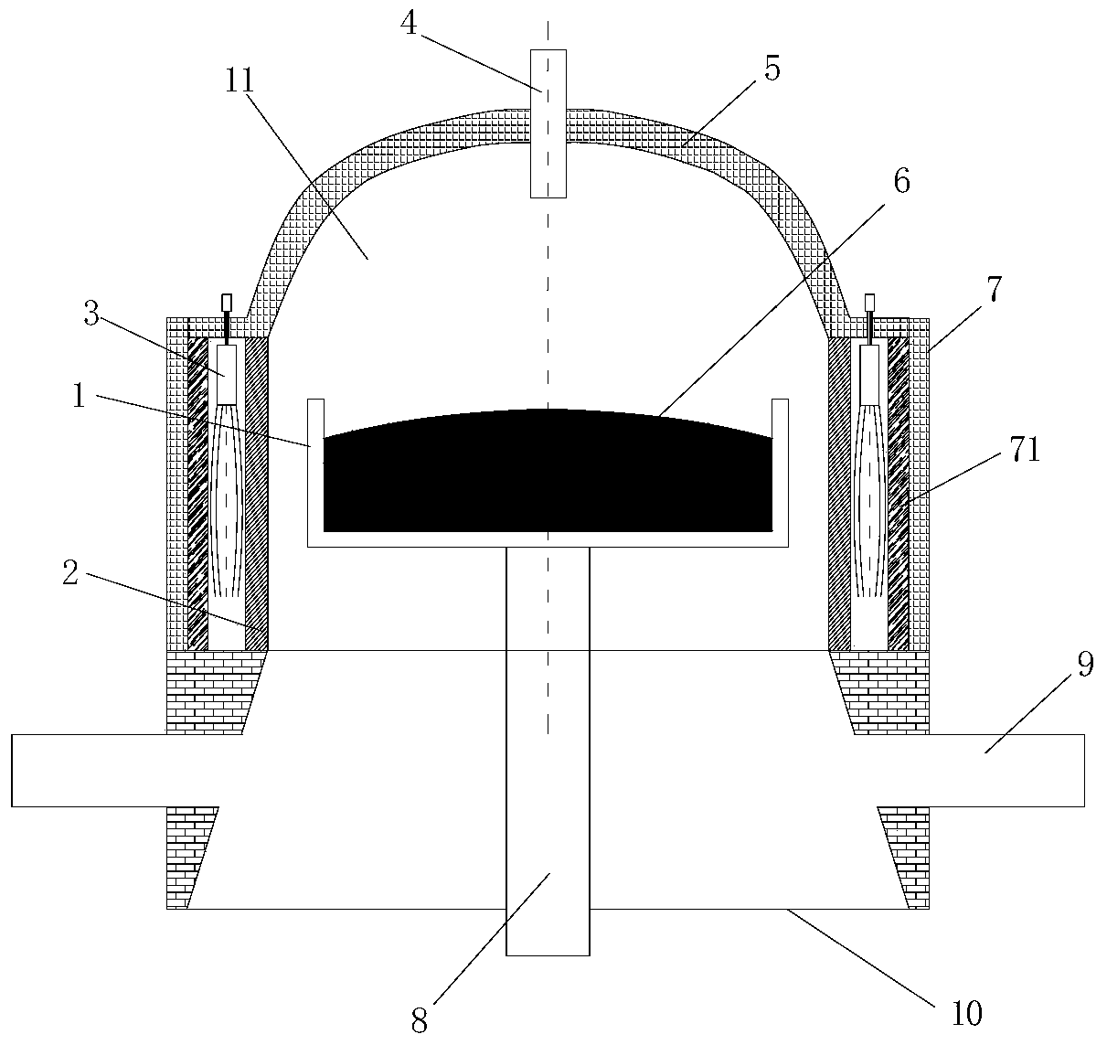
[0029] Figure 1 to Figure 3 It is a schematic structural diagram of deposition furnaces in different embodiments of the present invention. Such as Figure 1 to Figure 3 As shown, the deposition furnace for preparing quartz glass ingots includes:

[0030] Furnace body, the furnace body is made up of furnace roof 5, furnace wall 7 and furnace bottom 10, and furnace roof 5, furnace wall 7 and furnace bottom 10 encircle furnace hearth 11;

[0031] The burner 4 is arranged on the furnace roof 5;

[0032] The base rod 8 extends vertically from the furnace bottom 10...


PUM

PropertyMeasurementUnit
angleaaaaaaaaaa
angleaaaaaaaaaa
diameteraaaaaaaaaa

Abstract

The invention discloses a deposition furnace for preparing quartz glass ingots, which comprises: a furnace body, the furnace body is composed of a furnace top, a furnace wall and a furnace bottom, and the furnace top, furnace walls and furnace bottom form a furnace; a burner , arranged on the top of the furnace; the base rod extends vertically from the bottom of the furnace into the furnace, the base rod can move in the vertical direction relative to the furnace body, and the base rod can rotate with its axis as a rotation axis; The deposition base is arranged on the top of the base rod and is fixedly connected with the base rod. The diameter of the deposition base is larger than the diameter of the base rod. The deposition base provides a basis for the deposition of quartz glass ingots; the auxiliary heating device is in the furnace It is arranged around the periphery of the deposition base and is used to increase the edge temperature of the quartz glass deposition mound. The invention reduces the temperature gradient of the deposition surface, improves the consistency of the component distribution of the quartz glass ingot, and produces the quartz glass ingot with uniform radial and axial structures.

Description

technical field [0001] The invention relates to the technical field of quartz glass ingot preparation, in particular to a deposition furnace for preparing quartz glass ingot. Background technique [0002] High-uniform synthetic quartz glass is an irreplaceable key basic material in high-tech fields such as aerospace, nuclear technology, lasers, and precision instruments. Optical inhomogeneity seriously affects the imaging quality of optical systems. [0003] At present, the melting methods of synthetic quartz glass ingot mainly include horizontal deposition furnace chemical vapor deposition method and vertical deposition furnace chemical vapor deposition method. Since the horizontal deposition furnace chemical vapor deposition method cannot produce large-sized, high-weight quartz glass ingots, and the furnace temperature is low, the energy consumption is large and the efficiency is low, it has been gradually replaced by the vertical deposition furnace chemical vapor depositi...

Claims


Application Information

Patent Timeline
Patent Type & Authority Patents(China)
IPC IPC(8): C03B5/00
Inventor 王玉芬聂兰舰向在奎饶传东王宏杰刘飞翔
Owner CHINA BUILDING MATERIALS ACAD
Why Eureka
Try Eureka