Clutch type formwork trolley, trolley assembly and underground passage concrete construction method

A formwork trolley and underground passage technology, which is applied in underground chambers, earthwork drilling, tunnels, etc., can solve the problems of high cost, long construction period, and overall demoulding of formwork trolleys, so as to save construction time and improve construction efficiency. Efficiency, the effect of achieving continuity

Active Publication Date: 2015-11-11
SHANGHAI MECHANIZED CONSTR GRP
4 Cites 10 Cited by

AI-Extracted Technical Summary

Problems solved by technology

[0004] The purpose of the present invention is to provide a clutch-type formwork trolley, trolley components and a concrete construction method for an underground passage ...

Abstract

The invention discloses a clutch type formwork trolley, a trolley assembly and an underground passage concrete construction method, and belongs to the technical field of tunnel building concrete construction equipment. The formwork trolley comprises a top formwork trolley and side formworks, wherein the side formworks are distributed at the two sides of the top formwork trolley; a moving guide rail is arranged at the bottom of each side formwork; and each moving guide rail is matched with moving pulleys arranged at the lower end of the top formwork trolley to drive the corresponding side formwork to longitudinally move. The formwork trolley assembly comprises two top formwork trolleys coaxially arranged in the longitudinal direction of an underground passage and a set of side formworks, wherein the moving pulleys arranged at the lower ends of the two top formwork trolleys are in mutual butt joint, so that the side formworks longitudinally slide on the formwork trolley assembly. The construction method comprises the following steps of: firstly installing the formwork trolley assembly in place; then, performing concrete casting of a first construction section; next, performing demoulding on the side formworks, and moving the side formworks on the top formwork trolleys of the second construction section to be installed; then, casting the second construction step; and circulating the operations in such a way until the concrete construction of the whole underground passage is completed.

Application Domain

Technology Topic

Image

  • Clutch type formwork trolley, trolley assembly and underground passage concrete construction method
  • Clutch type formwork trolley, trolley assembly and underground passage concrete construction method
  • Clutch type formwork trolley, trolley assembly and underground passage concrete construction method

Examples

  • Experimental program(2)

Example Embodiment

[0035] Example one
[0036] Combine below Figure 1 to Figure 5 A detailed description will be given to the construction method of the clutch type formwork trolley, trolley assembly and underground passage concrete of the present invention.
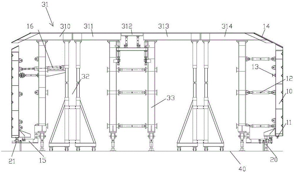
[0037] Such as figure 1 As shown, a clutch type formwork trolley used for concrete pouring construction of an underground passage includes a top formwork trolley 31, a side formwork 10 and a vertical support rod 20. The side formwork 10 is distributed on both sides of the top formwork trolley 31 and The wooden formwork 14 is connected to the top formwork trolley 31; the bottom of the side formwork 10 is provided with a moving guide 11, which cooperates with the moving pulley 21 provided on the vertical support rod 20 to drive the side formwork 10 to move longitudinally.
[0038] The top template trolley 31 includes at least two top template trolley units arranged side by side and detachably connected. Each top template trolley unit includes a top template 31, a traveling mechanism 32, and a column 33. The traveling mechanism 32 and the column 33 are both Tightly supported under the top template 31, the movable pulley 21 is detachably mounted on the column 33 close to the side template 10.
[0039] Specifically, according to the construction requirements, the concrete pouring work of the underpass bottom plate 40 is completed first, and then the concrete pouring construction of the underpass structure roof and structural side walls is carried out by using a clutch formwork trolley. The template trolley is assembled on the bottom plate 40 of the underground passage. Because the curing time required for the concrete of the structural roof and the structural side wall to reach the design strength is different, according to the construction specification, the curing time of the structural side wall concrete is usually half of the structural roof concrete curing time. Therefore, after the concrete strength of the structural side wall of the current construction section reaches the design requirements, the side formwork 10 is removed, cleaned and sent to the next construction section for the construction of the structural side wall concrete, thereby saving construction time. The top template 31 and the side template 10 are connected by a wooden template 14, which increases the lateral movement space of the side template 10, facilitates the cleaning of the side template 10, reduces the time for assembling the aforementioned templates on site, and simplifies the processing difficulty.
[0040] In particular, the side formwork 10 also includes a lateral telescoping device (not shown). The lateral telescoping device includes a lateral moving bracket 15 installed on the column 33 and a side formwork moving cylinder 16. The side formwork moving cylinder 16 is detachably mounted on Between the column 33 and the walking mechanism 32, the side template moving cylinder 16 drives the side template 10 to expand and contract along the lateral moving bracket 15.
[0041] Of course, in order to prevent the side template 10 from tipping over when it moves, it is ensured that the side template 10 moves linearly along the movable pulley 21 provided on the column 33 until it reaches the designated position. The side template 10 close to the column 33 is provided with an upper moving guide rod. 13.
[0042] Preferably, in order to satisfy the force stability of the side formwork 10, the side formwork 10 is detachably connected to the column 33 on the same side through the lateral support rods 12. The detachable connection in this embodiment includes hinged connection, bolt connection, pin shaft connection, etc., and the present invention is not limited herein.
[0043] In particular, in order to further shorten the concrete construction period of the underground passage, save costs, and improve the construction quality, another embodiment of the present invention provides a trolley assembly. The trolley assembly includes two top formwork trolleys and a set of side formwork coaxially arranged along the longitudinal direction of the underground passage. The moving pulleys at the lower ends of the two top formwork trolleys are connected to each other, so that the side formwork slides longitudinally on the formwork trolley assembly . The two top template trolleys are top template trolley one and top template trolley two. When the concrete strength of the side wall of the construction section where the top form trolley 1 is located reaches the design requirements, for example, 8-12 days, remove the side form 10 on the top form trolley 1, and shrink the side form 10 laterally for a certain distance, for example, 70 Cm, clean the side formwork 10, and then move the side formwork 10 along the moving pulley 21 to the top formwork trolley 2 in the next construction section, and install it on the top formwork trolley two, and proceed to the top formwork trolley 2 position Pouring of the structural roof and side wall concrete of the construction section. When the concrete strength of the side wall of the structure meets the design requirements, repeat the related operations of the opposite side formwork 10; at the same time, the concrete strength of the structural roof of the construction section where the top formwork trolley is located will also meet the design requirements, so it can Remove the top form 31 of the top form trolley 1, and make the top form 31 pass through the top form trolley 2 under the driving of the traveling mechanism 32 to enter the third construction section, and place the side form 10 in the construction section where the top form trolley 2 is located. Move to the third construction section, and install it on the top formwork trolley 1, and the underground passage structure roof and structural side walls of the third construction section will be integrally poured with concrete. That is to say, the trolley assembly includes two top formwork trolleys and a set of side formwork 10. The two top formwork trolleys are arranged one behind the other and are located in adjacent construction sections; through a set of side formwork 10 and two The top formwork trolley realizes alternate cycle construction, realizes construction continuity, and improves construction efficiency.
[0044] Further, the top template trolley includes a top template trolley unit 310, a top template trolley unit two (not shown), and a top template trolley unit three 314 that are detachably connected in sequence. The top template trolley unit two includes The one detachable middle roof form trolley unit 311, the detachable small roof 312, and the second middle roof form trolley unit 313 are detachably connected. After the concrete strength of the structural roof meets the design requirements, the roof form 31 is removed and the roof form trolley is decomposed, so that the width of the decomposed roof form trolley unit can be smaller than the aisle formed by the column 33 of the other roof form trolley Therefore, it is convenient for the decomposed top template trolley unit to pass through another top template trolley and be installed. In particular, when there is a lattice column in the middle of the local lower channel, the decomposed roof formwork trolley can bypass the lattice column and travel to the designated construction section by removing the detachable small roof.

Example Embodiment

[0045] Example three
[0046] Continue to combine below Figure 1 to Figure 5 The concrete construction method of the underground passage is explained in detail. The concrete construction method of the underground passage is to divide the underground passage into several construction sections for continuous construction, including the following steps:
[0047] S001: Lay the bottom plate 40 of the underground passage, and place the trolley components on the bottom plate 40. The two trolley components are the top formwork trolley 1 and the top formwork trolley 2, so that the top formwork trolley 1 is located in the first construction section. Top formwork trolley 2 is located in the second construction section;
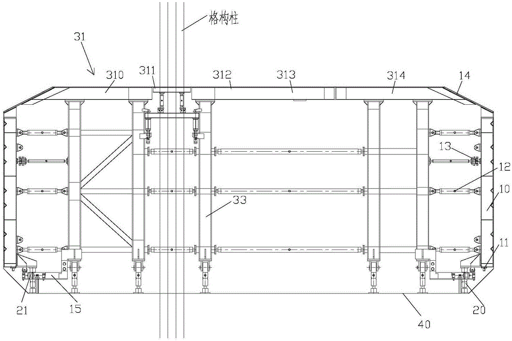
[0048] S002: Please continue to refer figure 2 , Pouring concrete in the first construction section to form the structural side wall and structural roof of the first construction section at one time;
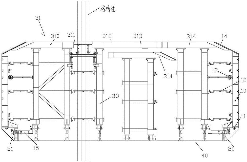
[0049] S003: Please continue to refer figure 1 After the concrete strength of the structural side wall of the first construction section meets the requirements, demould the side form 10 and move the side form 10 longitudinally to the second construction section, and install the side form on the top formwork trolley two;
[0050] S004: Please continue to refer figure 2 , Pouring concrete in the second construction section to form the structural side wall and structural roof of the second construction section at one time;
[0051] S005: Please continue to refer Figure 3 to Figure 5 After the structural roof concrete strength of the first construction section meets the requirements, perform the demoulding work of the top form 31, and move the top form trolley 1 through the top form trolley 2 to the third construction section. At the same time, the second After the concrete strength of the structural side wall of the construction section meets the requirements, demould the side form 10 and move the side form 10 longitudinally to the third construction section, and install the side form 10 on the top form trolley 1;
[0052] S006: Repeat S002 to S005 until the concrete construction of the entire underground passage is completed.
[0053] Particularly, in S003, between the demolding of the side template 10 and the longitudinally moving side template 10, it also includes moving the side template 10 laterally toward the middle of the template trolley for a predetermined distance (for example, transverse shrinkage of 70 cm) to clean the side template 10.
[0054] Further, S005 also includes first splitting the top template trolley 1 into top template trolley unit 310, middle top template trolley unit 311, detachable small top plate 312, middle top template trolley unit two 313, and top template Trolley unit three 314; then, the split top form trolley one passes through the top form trolley two in turn and moves to the third construction section.
[0055] In summary, the clutch formwork trolley of the present invention is used for concrete construction of underground passages and includes a top formwork trolley and a side formwork. The side forms are distributed on both sides of the top formwork trolley and pass through the wooden formwork and the top formwork trolley. Connection; the bottom of the side template is provided with a movable guide rail, which cooperates with a movable pulley set at the lower end of the top template trolley to drive the side template to move longitudinally. After the concrete strength of the structural side wall of the current construction section reaches the design requirements, the side formwork is removed, and the rear side formwork is cleaned along the detachable movable pulley installed at the lower end of the top formwork for the next construction section for the side wall concrete pouring construction , Thus saving construction time. The top template and the side template are connected by a wooden template, which increases the space for lateral movement of the side template, facilitates the cleaning of the side template, reduces the time for assembling the aforementioned templates on site, and simplifies the processing difficulty. The trolley assembly of the present invention includes two top formwork trolleys and a set of side formwork coaxially arranged along the longitudinal direction of the underground passage. The moving pulleys at the lower ends of the two top formwork trolleys are connected to each other, so that the side formwork is in the formwork trolley assembly Swipe up vertically. By coaxially setting up two roofing formwork trolleys one after the other along the length of the underground passage, and making the two roofing formwork trolleys located in adjacent construction sections respectively, so as to pass two roofing formwork trolleys and one set of side The formwork can realize the alternate cycle construction. The top formwork and the side formwork of the formwork trolley component are demolded according to the curing time of their respective pouring concrete, so that after completing the construction of one section, they will independently advance to the next section to achieve the construction. The continuity of the construction improves the construction efficiency. The concrete construction method of the underground passage, the top form and the side form of the trolley component are demolded according to the curing time of the respective pouring concrete, so that after completing the construction of one section, they are independently advanced to the next section for construction, which is similar to the formwork in the prior art. Compared with the construction method of integral demoulding and integral advancement of the trolley, the construction method of the present invention shortens the construction period, saves the cost, and is convenient to operate, safe and reliable.

PUM

no PUM

Description & Claims & Application Information

We can also present the details of the Description, Claims and Application information to help users get a comprehensive understanding of the technical details of the patent, such as background art, summary of invention, brief description of drawings, description of embodiments, and other original content. On the other hand, users can also determine the specific scope of protection of the technology through the list of claims; as well as understand the changes in the life cycle of the technology with the presentation of the patent timeline. Login to view more.

Similar technology patents

Distance-adjustable laser level

PendingCN109443330ASimple structureShorten construction timeReference line/planes/sectorsEngineeringLaser line
Owner:广西南宁联纵消防设备有限公司

Classification and recommendation of technical efficacy words

  • Reduce construction costs
  • Shorten construction time
Why Eureka
Try Eureka