System and method for large-scale radar antenna deformation real time measurement

A radar antenna, real-time measurement technology, applied in measurement devices, instruments, optical devices, etc., to achieve the effects of small equipment, fast data processing, and simple principles

Inactive Publication Date: 2015-11-11
CHINA ELECTRONIC TECH GRP CORP NO 38 RES INST
View PDF5 Cites 22 Cited by
  • Summary
  • Abstract
  • Description
  • Claims
  • Application Information

AI Technical Summary

Problems solved by technology

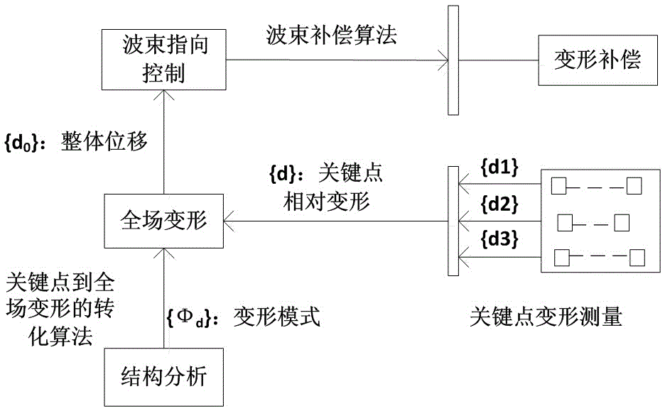
[0004] The primary purpose of the present invention is to provide a large-scale radar antenna deformation real-time measurement system that can meet the measurement requirements of large radar array, high precision, and real-time performance, and solve the problem of small deformation detection of large-scale radar antenna structures

Method used


Image

  • System and method for large-scale radar antenna deformation real time measurement
  • System and method for large-scale radar antenna deformation real time measurement
  • System and method for large-scale radar antenna deformation real time measurement

Examples


Embodiment 1

[0030] Such as Figure 4 As shown, this embodiment is directed to a large aluminum skeleton 4 antenna with an array size of 10 meters by 10 meters. Considering the front size, measurement range and front deformation mode comprehensively, 12 PSD laser sensors 1 are arranged corresponding to the deformation key points of the upper skeleton 4, and 12 laser light sources 2 are arranged at the bottom of the front where the deformation is small, so that the laser light source 2 laser The point is perpendicularly incident on the center of the PSD laser sensor 1 . At the same time, the PSD laser sensor 1 is arranged between the laser light sources 2 to measure the relative deformation between the 12 light sources. The deformation value is relatively small, and finally a measurement network is formed on the front surface. When a certain load is applied by the pallet loading device 6 at the rear of the skeleton 4, the skeleton 4 is deformed, and the measurement system obtains the defor...


PUM


Abstract

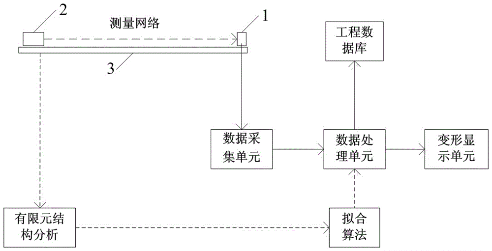
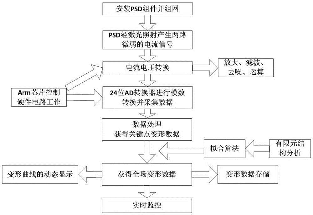
The invention relates to a large-scale radar antenna deformation real time measurement system, comprising a plurality of PSD laser sensors for measuring the deformation amount of deformation key points and laser sources corresponding to the deformation key points on one-to-one basis; the output terminal of the PSD laser sensor is connected to the input terminal of a data collection unit; the output terminal of the data collection unit is connected to the input terminal of the data processing unit; the output terminal of the data processing unit is connected to the input terminal of a deformation display unit for displaying whole deformation curve surface of an antenna array on real time. The invention also discloses a large-scale radar antenna deformation real time measurement method. The invention converts the whole field deformation measurement of a super big array to a series of relative deformation measurements corresponding to the key points, which is simple in theory, small in devices, high in accuracy, fast in processing data, and can satisfy the real time performance measurement needs for big array surfaces and high accuracy.

Description

technical field [0001] The invention relates to the technical field of real-time measurement of large-scale radar phased array antenna deformation, in particular to a system and method for real-time measurement of large-scale radar antenna deformation. Background technique [0002] Various factors such as gravity load, wind load, thermal load, and attitude change will affect the accuracy of the antenna, especially for radars that require high precision, and the impact of antenna structure deformation on its performance cannot be ignored. The requirements for structural design generally need to control its deformation within 1 / 10 to 1 / 20 of the wavelength. For example, for high-band antennas such as X-band antennas (wavelength about 36mm), the deformation needs to be controlled to be less than 1.8mm, and for Ka-band ( 9mm) even need to make its deformation less than 0.45mm. As the array diameter increases, in order to ensure the accuracy of the array, the contradiction betwe...

Claims


Application Information

Patent Timeline
Patent Type & Authority Applications(China)
IPC IPC(8): G01B11/16
Inventor 胡劲松王璐缪泓查金水张根烜
Owner CHINA ELECTRONIC TECH GRP CORP NO 38 RES INST
Why Eureka
Try Eureka