Check patentability & draft patents in minutes with Patsnap Eureka AI!

Laser dust sensor

A dust sensor and sensor technology, which is applied in scientific instruments, measuring devices, suspension and porous material analysis, etc., can solve the problems of increasing the resistance of the sampling system, reducing the sampling flow rate, and the large volume of the airflow flow sensor, etc., to achieve long-term reliability operation, good sensor accuracy, and the effect of reducing the failure rate

Inactive Publication Date: 2015-11-11
QUALITY AIR SHENZHEN TECH CO LTD
View PDF0 Cites 6 Cited by
  • Summary
  • Abstract
  • Description
  • Claims
  • Application Information

AI Technical Summary

Problems solved by technology

[0005] 1. The volume of the airflow flow sensor is relatively large, so the sensor cannot be miniaturized;
[0006] 2. The cost of the gas flow sensor is relatively high, which increases the overall cost of the sensor;
[0007] 3. Installing a gas flow sensor in the sampling channel will increase the resistance of the sampling system, resulting in a decrease in the sampling flow rate and a decrease in the stability of the sensor, or in order to ensure the sampling flow rate, a larger sampling pump or fan needs to be selected

Method used


Image

  • Laser dust sensor
  • Laser dust sensor

Examples


Embodiment Construction

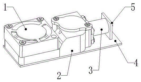
[0025] Such as figure 1 As shown, a laser dust sensor includes a fan 1, a detection cavity 2, a laser installation structure 3, a detection circuit board 4 with a photosensitive element microcontroller, and a laser 5.

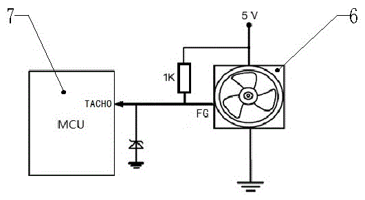
[0026] figure 2 A typical connection circuit principle of a single-chip microcomputer and a fan adopting the scheme of the present invention is shown. The fan 6 has an FG speed detection signal output, which is connected to the TACHO interface of the single-chip microcomputer MCU7. The single-chip microcomputer MCU7 collects the FG signal output by the fan 6 and uses the FG The signal corrects the sensor output in real time.

[0027] figure 2 The circuit in the circuit uses 5V DC to supply power to the fan 6. One wire of the fan 6 is connected to 5V, one wire is grounded, and the third wire is connected to the single-chip microcomputer MCU7. voltage diode.

[0028] The described real-time correction method is:

[0029] When the sensor is calibrated, the ...


PUM


Abstract

The invention provides a laser dust sensor which includes a laser device, a photo-sensitive component, a detection circuit, a single chip microcomputer and a fan. The fan having an FG rotation speed detection signal output. The single chip microcomputer collects the FG signal outputted from the fan and corrects an output result of the sensor through the FG signal. The correction method of correcting the output result of the sensor through the FG signal includes the steps of: recording the FG value A of the fan during calibration by the sensor; when the sensor works, obtaining a real-time FG value B by the single chip microcomputer; setting dust value of the sensor before FG signal correction as x and calculating the corrected dust value x1=x*A / B. In the invention, the fan rotation speed signal FG is used for representing actual sampling flow rate change, so that the system is free of resistance increase and is less in cost increase. The invention achieves further miniaturization and low cost of the sensor with better accuracy of the sensor being achieved.

Description

technical field [0001] The invention relates to the field of gas sensors, in particular to a laser dust sensor. Background technique [0002] Laser transmission method and scattering method are common measurement methods for measuring the content of dust particles in the air. When the gas flows through the area irradiated by the laser beam, the dust particles in the gas will cause the laser light to scatter. A photoelectric element is used to receive the transmitted light or scattered light. The intensity of light or scattered light, that is, the output electrical signal of the photoelectric element, can be converted to the amount of dust in the unit flow. [0003] Since the output value of the sensor is the dust content per unit flow rate, whether the actual sampling flow rate of the sensor is consistent with the flow rate when the sensor is calibrated will have a great influence on the accuracy. Therefore, in order to eliminate the influence of flow deviation on sensor ou...

Claims


Application Information

Patent Timeline
Patent Type & Authority Applications(China)
IPC IPC(8): G01N15/06
Inventor 徐宗燕
Owner QUALITY AIR SHENZHEN TECH CO LTD
Features
  • R&D
  • Intellectual Property
  • Life Sciences
  • Materials
  • Tech Scout
  • Unparalleled Data Quality
  • Higher Quality Content
  • 60% Fewer Hallucinations
Learn More