
S-wave band miniature balanced filter power divider

A microwave power divider and balanced filter technology, which is applied to waveguide-type devices, circuits, connecting devices, etc., can solve the problems affecting the use range of the power divider, the power is not large enough, and the development of the power divider is limited. Mass production, high reliability, small size effect

Inactive Publication Date: 2015-11-11
NANJING UNIV OF SCI & TECH
View PDF8 Cites 1 Cited by
  • Summary
  • Abstract
  • Description
  • Claims
  • Application Information

AI Technical Summary

Problems solved by technology

[0004] But so far, there is still a lot of room for development in the technology of power dividers, and the development of modern communications requires higher performance power dividers
For example, if the withstand power is not large enough and the frequency band is not wide enough, it will affect the scope of use of the power divider and limit the development of the power divider

Method used


Image

  • S-wave band miniature balanced filter power divider
  • S-wave band miniature balanced filter power divider
  • S-wave band miniature balanced filter power divider

Examples


Embodiment 1

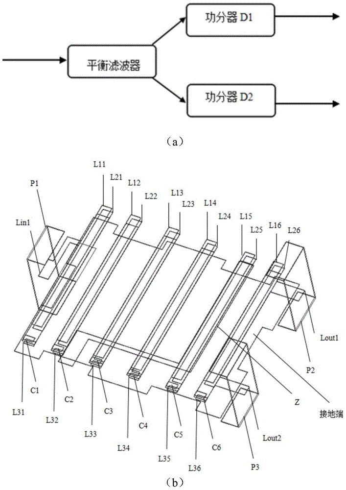
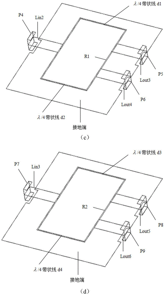
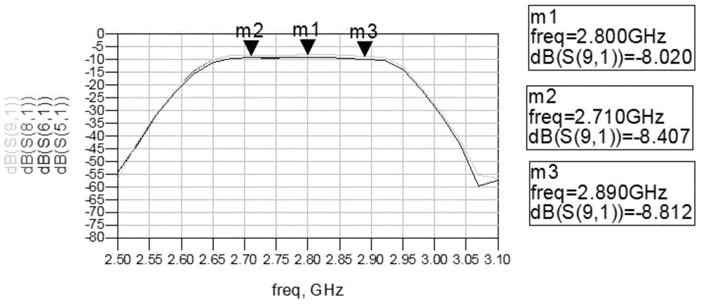
[0024] The size of the balanced filter in the S-band miniature balanced filter power divider of the present invention is only 3.23mm×4.5mm×1.53mm, and the size of the power divider is only 14.02mm×12.92mm×1.62mm. combine Figure 2-5 , the performance of the S-band miniature balanced filter power splitter of the present invention is as follows: the passband bandwidth is 2.7GHz~2.9GHz, the third output port P5 of the 50 ohm impedance of the surface mount, the fourth output port P6 of the 50 ohm impedance of the surface mount , The output waveforms of the surface-mounted 50-ohm impedance fifth output port P8 and the surface-mounted 50-ohm impedance sixth output port P9 in the passband are basically the same, and the return loss of the input port is better than 10dB; in the passband, Surface mount 50 ohm impedance third output port P5, surface mount 50 ohm impedance fourth output port P6 have approximately the same phase, surface mount 50 ohm impedance fifth output port P8, surfac...


PUM


Abstract

An S-wave band miniature balanced filter power divider disclosed by the present invention comprises a balanced filter and two miniature microwave power dividers, wherein the balanced filter comprises a first input port, a first input inductor, six-stage successive connected parallel resonant unit, a first output inductor, a second output inductor, a Z-shaped interstage coupling strip line, a first output port and a second output port. The first output port of the balanced filter is connected with the input port of the first microwave power divider, and the second output port is connected with the input port of the second microwave power divider. The two miniature microwave power dividers are composed of the compact three-dimensional stereo integrated structures. The above structures are all realized by a multi-layer low temperature co-fired ceramic technology. The S-wave band miniature balanced filter power divider of the present invention has four output signals of same power, has the advantages of being able to generate the quadrature phase, being easy to debug, being small in insertion loss, and is suitable for a system of the corresponding microwave frequency band, such as a communication system, a satellite communication system, etc.

Description

technical field [0001] The invention relates to a power divider, in particular to an S-band miniature balanced filter power divider. Background technique [0002] A power splitter (referred to as a power splitter) is an important microwave passive device. Power splitters are widely used in the field of wireless communications, mainly including microwave power amplification, linearization circuits, etc. From the mid-1950s to the 1960s, the world's first power splitter, called Wilkinson (Wilkinson) power splitter, was proposed in the world, which was realized by using the impedance transformation characteristics of a quarter-wavelength transmission line. With the rapid development of communication technology and the intensification of competition in the communication industry, new requirements have been put forward for the performance of Wilkinson power splitters. The traditional Wilkinson power splitter can only work in a single frequency band and its odd harmonics, which i...

Claims


Application Information

Patent Timeline
Patent Type & Authority Applications(China)
IPC IPC(8): H01P5/12
Inventor 许心影周衍芳戴永胜刘毅乔冬春李博文陈烨
Owner NANJING UNIV OF SCI & TECH
Learn More