Satellite navigation circularly polarized microstrip antenna

A microstrip antenna and satellite navigation technology, applied in the field of satellite navigation, can solve the problems of narrowing the antenna beam width, sacrificing the antenna gain, radiation efficiency and axial ratio, etc., to reduce the antenna size, expand the working bandwidth, and achieve high radiation efficiency. Effect

Inactive Publication Date: 2015-11-11
OLINKSTAR CORP
View PDF4 Cites 7 Cited by
  • Summary
  • Abstract
  • Description
  • Claims
  • Application Information

AI Technical Summary

Problems solved by technology

However, the method of using a medium with a high dielectric constant will sacrifice the gain, radiation efficiency and axial ratio of the antenna, and the antenna beam width will be narrowed

Method used


Image

  • Satellite navigation circularly polarized microstrip antenna
  • Satellite navigation circularly polarized microstrip antenna
  • Satellite navigation circularly polarized microstrip antenna

Examples


Embodiment Construction

[0026] Embodiments of the present invention will be further described in detail below in conjunction with the accompanying drawings.

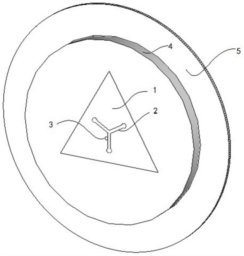
[0027] Such as figure 1 Shown is a schematic structural diagram of the circularly polarized microstrip antenna of the present invention. A satellite navigation circularly polarized microstrip antenna, comprising a microstrip antenna metal radiating plate 1, a dielectric substrate 4 and a metal reflective base plate 5, the metal radiating plate 1 and the metal reflective base plate 5 are respectively arranged on the upper surface and the lower surface of the dielectric substrate 4 ; The dielectric substrate 4 and the metal reflection bottom plate 5 of the present embodiment are circular, and the shape of the metal radiation plate 1 is a triangle, and the triangle metal radiation plate 1 is provided with a Y-shaped groove 2, and the Y-shaped groove includes three strip-shaped grooves, three The starting ends of the bar-shaped slots intersect and...


PUM


Abstract

The invention provides a satellite navigation circularly polarized microstrip antenna. A triangular Y-shaped groove microstrip radiation unit is adopted, which has the characteristics of high radiation efficiency, high low-elevation gain, wide band, wide wave beam and minimization, and is particularly suitable for receiving low-elevation satellite signals and increasing the center accuracy of an antenna phase. The satellite navigation circularly polarized microstrip antenna comprises a metal radiant panel, a dielectric substrate and a metal reflection bottom plate, wherein the metal radiant panel and the metal reflection bottom plate are arranged on the upper surface and the lower surface of the dielectric substrate respectively; the metal radiant panel is triangular; the triangular radiant panel is provided with a Y-shaped groove; the Y-shaped groove comprises three strip-shaped open grooves; the starting ends of the three strip-shaped open grooves converge in an intersecting way, and the tail ends point to the three edges of a triangle respectively; the triangular radiant panel provided with the Y-shaped groove is used for controlling surface current flow, and radiating circularly polarized waves; and the edges of the strip-shaped open grooves of the Y-shaped groove are provided with coaxial feeding points for feeding electromagnetic wave signals.

Description

technical field [0001] The invention belongs to the technical field of satellite navigation, and particularly relates to a circularly polarized microstrip antenna for satellite navigation. It is applicable to various navigation satellite systems including the GPS system of the United States, the Galileo system of Europe, the GLONASS system of Russia, and the Beidou system of China. Background technique [0002] Satellite navigation antennas are generally divided into two types: linear polarization and circular polarization. The implementation method of the linearly polarized antenna is simple, and it is generally used in non-professional navigation equipment such as mobile phones that do not require high positioning accuracy. Circularly polarized antennas are generally used in professional navigation equipment such as satellite navigation receivers. At present, the US GPS system, the Russian GLONASS system, and China's Beidou system all use circularly polarized waves to tr...

Claims


Application Information

Patent Timeline
Patent Type & Authority Applications(China)
IPC IPC(8): H01Q1/36H01Q13/08H01Q15/14H01Q1/38
Inventor 不公告发明人
Owner OLINKSTAR CORP
Why Eureka
Try Eureka