
Bent wing-type radio-frequency quadrupole accelerator

A radio frequency quadrupole and accelerator technology, applied in accelerators, electrical components and other directions, can solve the problems of cavity mechanical design and processing difficulty, difficult to guarantee processing accuracy, complex cooling system, etc., to improve reliability and stability, The effect of reducing the difficulty of processing and simple cooling system

Active Publication Date: 2015-11-11
科近泰基新技术有限公司
View PDF5 Cites 9 Cited by
  • Summary
  • Abstract
  • Description
  • Claims
  • Application Information

AI Technical Summary

Problems solved by technology

However, the cooling system of the four-rod RFQ accelerator is quite complicated. It generally consists of electrode cooling channels, support plate cooling channels, pad cooling channels and bottom plate cooling channels. great difficulty
At the beginning of this century, the American Argonne Laboratory (ANL) proposed a windowed four-wing RFQ acceleration structure, which is also suitable for low frequency ranges, but its disadvantage is also that the cooling system is complicated
[0003] Theoretically speaking, the traditional four-wing RFQ accelerator acceleration structure can also be used in the low-frequency field, and the acceleration structure has the advantages of simple and effective cooling system, but when it is applied in the low-frequency field, its cross-sectional size is often large. Take the four-wing RFQ accelerator at Michigan State University (MSU) as an example. Its operating frequency is 80.5MHz and the inner diameter of the cavity reaches 940mm. Welding furnace, the most important thing is that the processing accuracy is not easy to guarantee

Method used


Image

  • Bent wing-type radio-frequency quadrupole accelerator
  • Bent wing-type radio-frequency quadrupole accelerator

Examples


Embodiment Construction

[0016] The principles and features of the present invention are described below in conjunction with the accompanying drawings, and the examples given are only used to explain the present invention, and are not intended to limit the scope of the present invention.

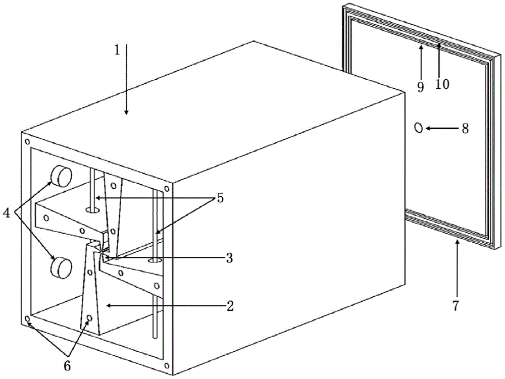
[0017] like figure 1 As shown, the above-mentioned curved airfoil radio frequency quadrupole accelerator is characterized in that it includes a cavity 1, four wings 2 are arranged in the cavity 1, and end plates 7 are respectively arranged at both ends of the cavity 1 , the center of each end plate is provided with a beam hole 8, the center line of the two beam holes is on the same line as the central axis of the cavity 1; the cavity 1 is also provided with a π-mode stabilizing rod 5 and used to adjust the frequency tuner 4.

[0018] Further, the cavity 1 and each end plate 7 are fixedly connected by screws, and a high-frequency sealing ring 9 and a vacuum sealing ring 10 are arranged between the cavity 1 and each ...


PUM


Abstract

The invention relates to the technical field of an acceleration mechanism of an ion accelerator, in particular to a bent wing-type radio-frequency quadrupole accelerator. The bent wing-type radio-frequency quadrupole accelerator is characterized by comprising a cavity, wherein four wings are arranged in the cavity, end plates are respectively arranged at the two ends of the cavity, a beam hole is arranged at the central position of each end plate, the central line of the two beam holes and the central axis of the cavity are on the same straight line, and a Pi-model stabilization rod and a tuner for adjusting frequency are further arranged on the cavity. By bending wings at pole head parts, the cross section size of the cavity is greatly reduced on the condition of no change on the total transverse length of the wings, and the bent wing-type radio-frequency quadrupole accelerator is very suitable for low-frequency beams; and meanwhile, due to the compatibility with the advantages of simplicity and effectiveness of a cooling system of the traditional four-wing radio-frequency quadrupole acceleration mechanism, the bent wing-type radio-frequency quadrupole accelerator is very suitable for a continuous-wave working state. Obvious advantages are shown on the aspects of reduction on processing difficulty of the radio-frequency quadrupole accelerator, reduction on engineering cost, improvement on running reliability and stability of a device and the like.

Description

technical field [0001] The invention relates to the technical field of ion accelerator acceleration mechanisms, in particular to a bent airfoil radio frequency quadrupole accelerator. Background technique [0002] The radio frequency quadrupole (RFQ) accelerator that appeared in the 1970s played a huge role in promoting the rapid development of accelerators in the world. The RFQ accelerator integrates beam acceleration, focusing and beam focusing, and is mainly suitable for the acceleration of low-energy beams, and is generally used as an injector for medium- and high-energy accelerators. At present, the accelerating structure of low-frequency RFQ accelerators commonly used by people is mainly a four-bar structure. When working in a continuous wave (CW) state, it is required that the RFQ accelerator must have a reasonable cooling system to effectively deal with the large amount of heat generated by the cavity during continuous operation. However, the cooling system of the ...

Claims


Application Information

Patent Timeline
IPC IPC(8): H05H7/06
Inventor 张周礼徐显波卢亮孙列鹏何源赵红卫石爱民
Owner 科近泰基新技术有限公司
Learn More