Individual abutment and manufacturing method thereof
A manufacturing method and abutment technology, applied in the field of biomedical engineering, can solve problems such as the inability to ensure the force direction and size accuracy of the abutment, affect the comfort of the patient's chewing effect, and make it difficult to control the manufacturing accuracy. Ideal roughness, good dimensional accuracy and high molding efficiency
- Summary
- Abstract
- Description
- Claims
- Application Information
AI Technical Summary
Problems solved by technology
Method used
Image
Examples
Embodiment 1
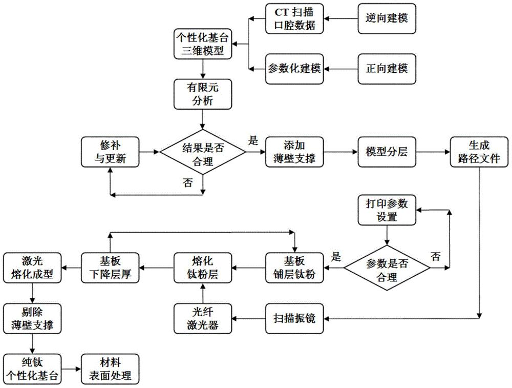
[0051] The manufacturing method of a personalized base station of this embodiment includes the following steps (see the flowchart figure 1 ):
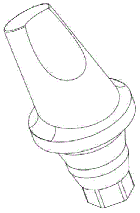
[0052] (1) Reverse modeling: CT scan the patient’s mouth to obtain a model of the patient’s jaw, including root depth, tooth inclination, and force inclination of occlusal contact. According to the jaw model, the doctor performs a computer on the jaw model. Simulate implantation of the implant, obtain the inclination angle of the implant, and perform the three-dimensional modeling of the abutment according to the implant to obtain the abutment model, such as figure 2 Shown
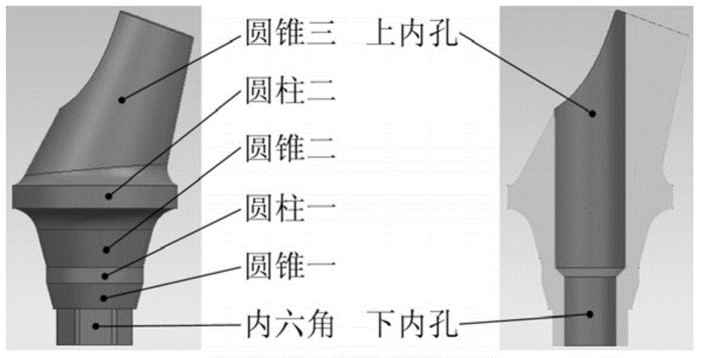
[0053] (2) Forward modeling: Using UnigraphicsNX as the platform, using its parametric modeling function, the geometric shape and size of each feature of the abutment model described in step (1) are expressed in variable parameters, using interactive graphics The design method realizes the parametric design process of the abutment, and realizes the intelligent and pers...
Embodiment 2
[0071] This embodiment is a method for manufacturing a personalized base station. The steps are the same as those in embodiment 1, except that:
[0072] The forming process in step (5) is as follows:
[0073] a. Lay titanium powder on the substrate, the thickness of the powder layer is 80μm, and use a scraper to evenly distribute the titanium powder layer;
[0074] b. At 0.5MPa, 20m 3 In the argon environment of / h, the high-precision scanning galvanometer is used to perform laser scanning molding (100W high-energy ytterbium-doped fiber laser) based on the path file generated by the three-dimensional model layer, and the metal titanium powder is melted by focused laser energy to form a flat The melting layer, the scanning parameters are:
[0075] The scanning speed is 10m / s; the laser beam diameter is 60μm; the repeat positioning accuracy is ±0.003mm; and the forming speed is 10ccm / h.
[0076] The method of surface treatment in step (7) is:
[0077] (i) Using the personalized base as th...
Embodiment 3
[0080] This embodiment is a method for manufacturing a personalized base station. The steps are the same as those in embodiment 1, except that:
[0081] The forming process in step (5) is as follows:
[0082] a. Lay titanium powder on the substrate, the thickness of the powder layer is 100μm, and use a scraper to evenly distribute the titanium powder layer;
[0083] b. At 1.5MPa, 30m 3 In the argon environment of / h, the high-precision scanning galvanometer is used to perform laser scanning molding (100W high-energy ytterbium-doped fiber laser) based on the path file generated by the three-dimensional model layer, and the metal titanium powder is melted by focused laser energy to form a flat The melting layer, the scanning parameters are:
[0084] The scanning speed is 5m / s; the laser beam diameter is 120μm; the repeat positioning accuracy is ±0.003mm; the forming speed is 20ccm / h.
[0085] The method of surface treatment in step (7) is:
[0086] (i) Using the personalized base as the a...
PUM
 Abstract
Description
Claims
Application Information
 - R&D
- Intellectual Property
- Life Sciences
- Materials
- Tech Scout
- Unparalleled Data Quality
- Higher Quality Content
- 60% Fewer Hallucinations
Browse by: Latest US Patents, China's latest patents, Technical Efficacy Thesaurus, Application Domain, Technology Topic, Popular Technical Reports.
© 2025 PatSnap. All rights reserved.Legal|Privacy policy|Modern Slavery Act Transparency Statement|Sitemap|About US| Contact US: help@patsnap.com


