Glass curtain wall cleaning device

A glass curtain wall and cleaning equipment technology, applied in the direction of walls, building maintenance, building components, etc., can solve the problems of casualties and property, easy to scratch the glass surface, difficult to work, etc., to improve operational safety and prevent people from falling. effect of accident

Inactive Publication Date: 2015-11-18
李伦伟
View PDF6 Cites 34 Cited by
  • Summary
  • Abstract
  • Description
  • Claims
  • Application Information

AI Technical Summary

Problems solved by technology

It is of course safer to implement this standard, but when the wind is strong, the work cannot be carried out, and the working date is greatly restricted, which sometimes affects the construction period.
Although very detailed safety regulations have been made in the standard, accidents of hanging baskets falling still occur from time to time, causing casualties and property losses
[0005] Some modern buildings pursue artistic shapes, the glass curtain wall is not necessarily vertical, it may be inclined, and the window cleaning machine is either close to the glass curtain wall due to gravity, which is easy to scratch the glass surface, or it is away from the glass curtain wall, and workers Can't reach the glass, very difficult to work with
[0006] The traditional window cleaning solution has poor safety and limited working conditions, so it is necessary to design a new window cleaning solution

Method used


Image

  • Glass curtain wall cleaning device
  • Glass curtain wall cleaning device
  • Glass curtain wall cleaning device

Examples


Embodiment 1

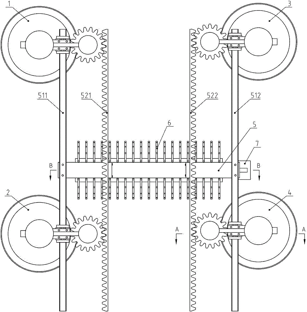
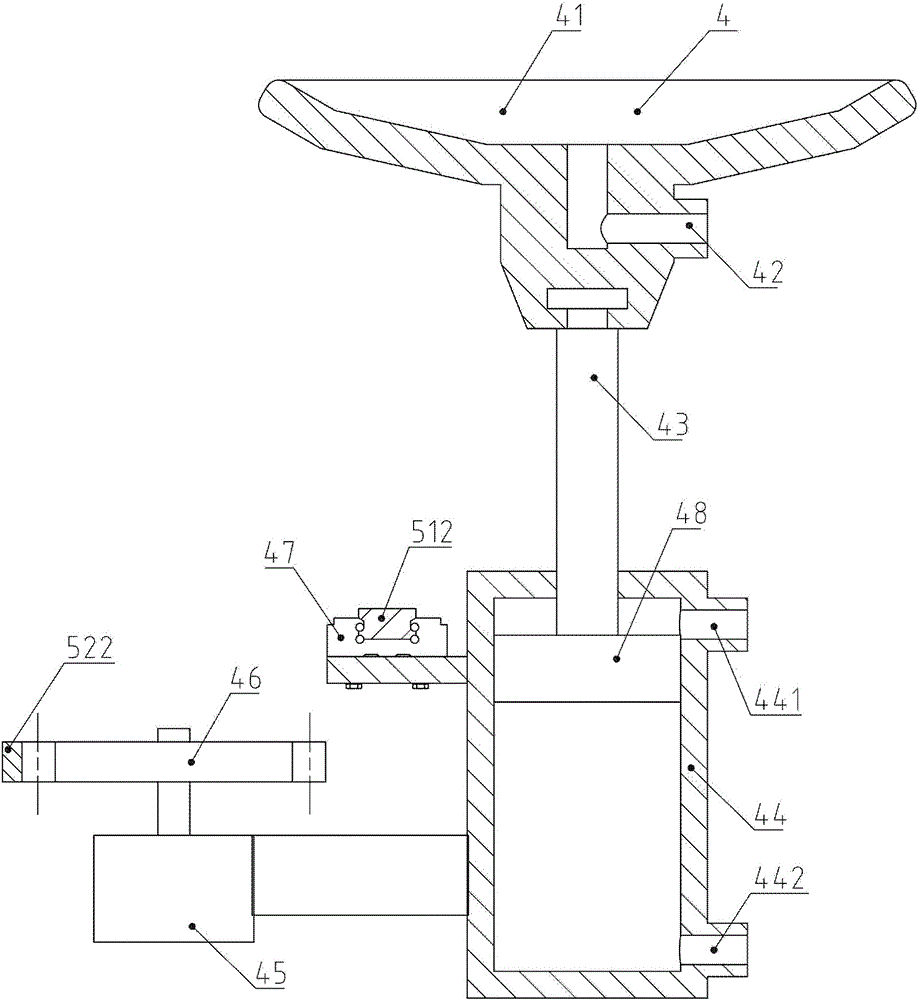
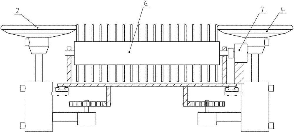
[0049] Embodiment 1: see Figure 1 to Figure 8 .

[0050] A glass curtain wall cleaning equipment, comprising a left upper suction cup assembly 1, a left lower suction cup assembly 2, a right upper suction cup assembly 3, a right lower suction cup assembly 4, a frame 5, a cleaning roller brush 6 and a cleaning motor 7; the frame 5 includes a left guide rail 511, Right guide rail 512, left rack 521 and right rack 522, these four parts are vertically arranged; Cleaning roller brush 6 has hairbrush on the circumferential surface, and cleaning roller brush 6 is connected with frame 5 through rotating pair, and cleaning motor 7 It is fixedly connected with the frame 5, and the output shaft of the cleaning motor 7 is connected with the shaft of the cleaning roller brush 6. When the cleaning motor 7 is energized and rotates, the cleaning roller brush 6 runs continuously, and the brush can continuously clean the surface of the glass curtain wall; The suction cup assembly 1, the lower...

Embodiment 2

[0072] Example 2: see Figure 9 to Figure 13 .

[0073] A glass curtain wall cleaning equipment, including a left upper suction cup assembly 1, a left lower suction cup assembly 2, a right upper suction cup assembly 3, a right lower suction cup assembly 4, a frame 5, a cleaning roller brush 6 and a cleaning motor 7; it also includes four walking cylinders 8 And cylinder rod-piston combination 9, walking cylinder barrel 8 and cylinder rod-piston combination 9 form walking cylinder, rear chamber air port 81 and front chamber air port 82 are arranged on walking cylinder barrel 8, and walking cylinder barrel 8 is fixedly connected with frame 5, The walking cylinder 8 and the cylinder rod-piston combination 9 form a moving pair. If the compressed air is connected to the air port 81 of the rear chamber or the air port 82 of the front chamber, the cylinder rod-piston combination 9 can reciprocate and translate along the moving pair; the cylinder rod-piston The end of the cylinder ro...

Embodiment 3

[0090] Embodiment 3: see Figure 14 .

[0091]This embodiment includes 6 suction cup assemblies, which are upper left suction cup assembly 1 , lower left suction cup assembly 2 , upper right suction cup assembly 3 , lower right suction cup assembly 4 , upper suction cup assembly 101 and lower suction cup assembly 102 . For a glass curtain wall with a relatively small area of ​​single glass, many splicing seams, and a large number of rivets, if the suction cup is just at the seam or rivet, the suction cup and the glass surface will not be in good contact, and the adsorption effect will be lost. Let it idle temporarily, the other five suction cups can still work, wait until the suction cup is moved to avoid seams or rivets, and then let it continue to work.

[0092] Other structures, functions and beneficial effects are the same as those in Embodiment 2.


PUM


Abstract

The invention belongs to the technical field of glass curtain wall cleaning devices, particularly relates to a glass curtain wall cleaning device. The glass curtain wall cleaning device comprises a plurality of sucker components, a rack, a cleaning roll brush and a cleaning motor, wherein the sucker components and the rack are connected through a moving pair and a walking device; brushes are arranged on the periphery of the cleaning roll brush; the cleaning roll brush is connected with the rack through a rotating pair; an output shaft of the cleaning motor is connected with a shaft of the cleaning roll brush; each sucker component comprises a sucker, an adsorption piston rod, an adsorption piston cylinder and an adsorption piston; each adsorption piston rod and the corresponding adsorption piston are combined to form a whole body, and then are combined with the corresponding adsorption piston cylinder to form a corresponding adsorption air cylinder; the tail end of each adsorption piston rod is fixedly connected with the corresponding sucker; a hole is formed in the center of each sucker, extends to the back surface of the sucker and is an adsorption hole; and two connecting holes are formed in each adsorption piston cylinder, are a front cavity hole and a rear cavity hole respectively, and respectively communicate with a front cavity and a rear cavity of the corresponding adsorption air cylinder. By the glass curtain wall cleaning device, fall accidents of personnel are stopped, operation safety is improved greatly, and work limiting conditions are reduced.

Description

technical field [0001] The invention belongs to the technical field of window cleaning machines, and in particular relates to a glass curtain wall cleaning device. Background technique [0002] The glass curtain wall is the outer protective wall of the building. It is not load-bearing and hangs up like a curtain, so it is also called a hanging wall. It is a light-weight wall with decorative effects commonly used in modern large and high-rise buildings. [0003] The outer surface of the glass curtain wall will rust or adhere to a layer of dust after a long time of use, which will affect the appearance and need to be cleaned. The traditional cleaning method is that the workers are suspended in mid-air close to the outer surface of the glass curtain wall by the window cleaning machine. There are cantilever beams and counterweight iron blocks on the top of the building, and steel wire ropes hang from the cantilever beams. The suspended parts are hanging baskets. The hanging bas...

Claims


Application Information

Patent Timeline
Patent Type & Authority Applications(China)
IPC IPC(8): E04B2/88E04G23/00
Inventor 李伦伟其他发明人请求不公开姓名
Owner 李伦伟
Why Eureka
Try Eureka