Coaxial-output rotation and revolution transmission method and device

A technology of coaxial output and transmission device, which is applied in the direction of transmission device, gear transmission device, rotary piston type/swing piston type pump components, etc., and can solve the problems of inability to actively output rotation and revolution, wear and deformation of rotor and stator inner cavity, Problems such as low stability of the transmission system, to achieve the effect of improving high-speed stability, simple and compact structure, and high transmission efficiency

Active Publication Date: 2015-11-18
SOUTH CHINA UNIV OF TECH +1
View PDF7 Cites 12 Cited by
  • Summary
  • Abstract
  • Description
  • Claims
  • Application Information

AI Technical Summary

Problems solved by technology

[0003] In traditional mechanical engineering devices, the rotor often needs to achieve rotation and revolution at the same time, but this rotation and revolution is caused by the coordinated movement of the actuator stator and rotor, while the transmission system of the construction machinery device is only composed of universal couplings. The device passively accepts the compound motion of the rotor shaft, but cannot actively output the rotation and revolution
When the traditional universal coupling-based transmission mechanism is connected to the rotation and revolution movement actuator, it can only rely on the meshing of the rotor and the stator to passively realize the revolution movement, and most of the axial load generated during transportation requires The stator and rotor bear the burden, and the overall stability of the transmission system is low, causing problems such as unstable operation of the rotor, wear and deformation of the inner cavity of the rotor and the stator, etc.
At present, there is no transmission device that coaxially outputs rotation and revolution and can bear axial load

Method used


Image

  • Coaxial-output rotation and revolution transmission method and device
  • Coaxial-output rotation and revolution transmission method and device
  • Coaxial-output rotation and revolution transmission method and device

Examples


Embodiment 1

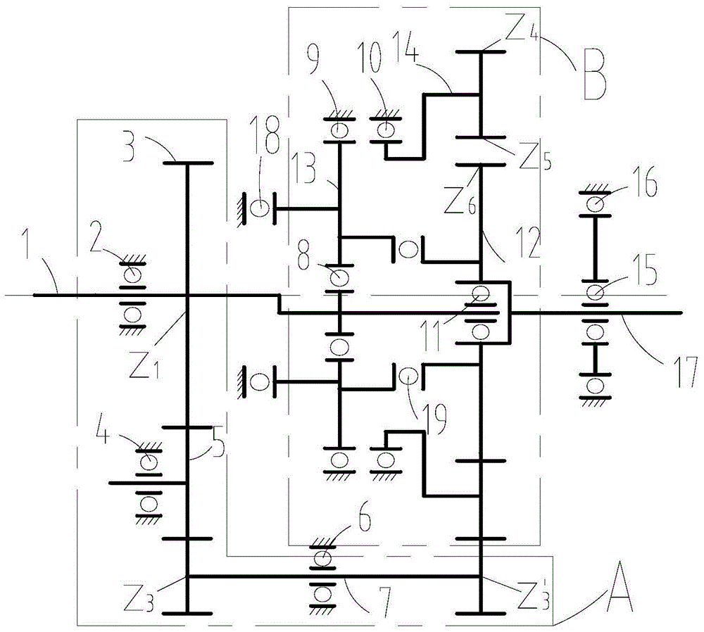
[0043] This embodiment is a transmission method for coaxial output rotation and revolution. The power input shaft is an eccentric shaft, including a connected main shaft and a shaft; the power output shaft revolves around the main shaft axis of the power input shaft, and at the same time the power output shaft revolves The axis rotates at a constant speed and reverses, and can bear axial loads, specifically:

[0044] The power input shaft is transmitted through the K-H-V planetary gear train with small tooth difference, so that the axis of the power output shaft coincides with the shaft axis of the power input shaft, and the power output shaft revolves around the main shaft axis of the power input shaft, and the revolution speed is the same as that of the power input shaft. At the same time, the active force of the power input shaft is superimposed by the transition gear system and the K-H-V planetary gear system with small tooth difference, so that the power output shaft produ...

Embodiment 2

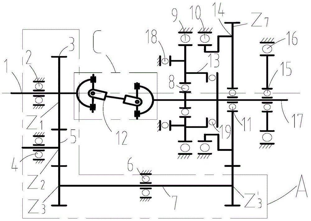
[0053] This embodiment is a transmission method for coaxial output rotation and revolution. The power output shaft revolves around the axis of the power input shaft, and at the same time, the power output shaft rotates at a constant speed and reverse around its own axis, and can bear axial loads. Specifically for:

[0054] The axis of the power output shaft is eccentric with respect to the axis of the power input shaft by using the power input shaft through the universal joint transmission system, and through the transmission of the transition gear system, the power output shaft revolves around the axis of the power input shaft, and the revolution speed and power The rotational speed of the input shaft is equal, and the revolution direction is opposite to that of the power input shaft; at the same time, the active force of the power input shaft passes through the transmission of the universal joint drive system, so that the power output shaft produces an autorotation motion at ...

Embodiment 3

[0066] This embodiment is an extruder formed by a combination of a coaxial output rotation and revolution transmission device and an eccentric rotor volume pulsation deformation plasticization transportation device.

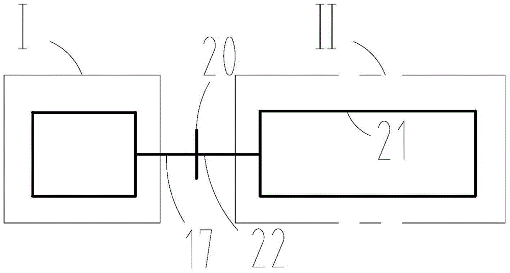
[0067] Wherein, the transmission device I with coaxial output rotation and revolution can adopt the transmission device described in embodiment 1 or embodiment 2. The eccentric rotor volume pulsating deformation and plasticizing transportation device II can adopt the eccentric rotor volume pulsating deformation and plasticizing transportation device disclosed in the patent application with application number 201410206552.8, such as Figure 4 As shown, a stator 21 and a rotor 22 are included.

[0068] Such as image 3 As shown, the transmission device I with coaxial output rotation and revolution is connected with the eccentric rotor volume pulsation deformation plasticization transportation device II through a connecting piece 20 . The power output shaft 17 is co...


PUM


Abstract

The invention relates to a coaxial-output rotation and revolution transmission method and device. The axis of a power output shaft and the axis of a crank of a power input shaft coincide; the power output shaft performs revolution around the axis of a spindle of the power input shaft, and the revolution speed is equal to the rotating speed of the power input shaft. Main power of the power input shaft is subjected to superposition of a transition gear train and a K-H-V small-tooth-difference planetary gear train, so that the power output shaft performs rotation movement which is equal to the power input shaft in speed and opposite to the power input shaft in direction; meanwhile, a rotation-revolution thrust bearing coaxial with the power output shaft and a thrust bearing coaxial with the spindle of the power input shaft are connected in series to bear axial loads. The coaxial-output rotation and revolution transmission device is mainly composed of the power input shaft, the transition gear train, the K-H-V small-tooth-difference planetary gear train, the series thrust bearing set, the power output shaft and the like. The device can form an extruder by being combined with an eccentric-rotor volume pulsation deformation plasticized transport device.

Description

technical field [0001] The invention relates to the technical field of mechanical transmission, in particular to a transmission method and device for coaxial output rotation and revolution. Background technique [0002] Modern mechanical transmission is widely used in mechanical engineering, mainly referring to the use of mechanical means to transmit power and motion. At present, most mechanical transmission mechanisms are single-input and single-output transmissions. However, in some special fields of mechanical engineering, the actuator is required to achieve coaxial rotation and revolution. For example, in the field of petrochemical industry, volumetric fluid conveying machinery mostly adopts a positive displacement pump structure, which uses the rotation and revolution of the rotor in the inner cavity of the stator to realize the volumetric fluid conveying process; in the field of polymer material processing machinery, some plasticizing conveying The motion device requ...

Claims


Application Information

Patent Timeline
Patent Type & Authority Applications(China)
IPC IPC(8): F16H1/32
CPCF16H1/32F16H2001/322F16H37/0833B29C48/2526F16C3/06F16C11/06F16C17/04F16H2001/323F04C2/1073F04C15/0065
Inventor 瞿金平张桂珍
Owner SOUTH CHINA UNIV OF TECH
Why Eureka
Try Eureka