
Resource distribution method and device oriented to multi-level elastic application of data center

A resource allocation and data-oriented technology, applied in the direction of data exchange network, data exchange through path configuration, digital transmission system, etc., can solve the problems that cannot achieve both efficiency and flexibility, and achieve the effect of avoiding over-allocation and ensuring simplicity

Inactive Publication Date: 2015-11-18
BEIJING INSTITUTE OF TECHNOLOGYGY
View PDF2 Cites 8 Cited by
  • Summary
  • Abstract
  • Description
  • Claims
  • Application Information

AI Technical Summary

Problems solved by technology

[0005] The purpose of the present invention is to solve the problem that the existing technology cannot realize the resource allocation that takes into account the requirements of both efficiency and flexibility, and proposes a resource allocation method for multi-level elastic applications in data centers. This method has high flexibility and strong adaptability. The advantages of high efficiency and flexibility

Method used

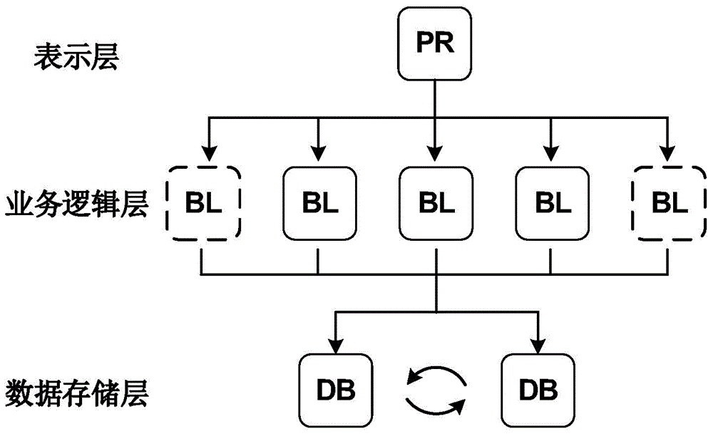
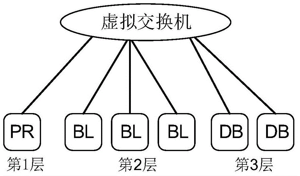
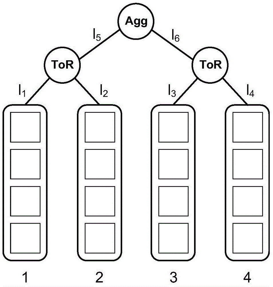

Image

  • Resource distribution method and device oriented to multi-level elastic application of data center
  • Resource distribution method and device oriented to multi-level elastic application of data center
  • Resource distribution method and device oriented to multi-level elastic application of data center

Examples


Embodiment 1

[0052] Such as Figure 6 Shown is the flow chart of the elastic resource allocation method of the present invention, according to this process, as image 3 The shown data center network topology structure is taken as an example to illustrate the implementation process of the present invention.

[0053] In this example, it is assumed that the bandwidth capacity of each physical link is 1Gbps. The user puts forward a request P as shown in Table 2. The request includes three layers, and the parameters of each layer are shown in Table 2. Take the layer 1 parameter T of the request P 1 = indicates the number of virtual machines requested by the user to be "always running", the number of virtual machines to be "running on demand", the bandwidth required for intra-layer communication, and the bandwidth required for inter-layer communication 1, 0, 0, 150 respectively, there is no threshold for loading the "run on demand" virtual machine. In addition, it can be seen from the table ...

Embodiment 2

[0120] Such as Figure 7 Shown is a schematic structural diagram of a resource allocation device for data center multi-level elastic applications of the present invention. It can be seen from the figure that the device includes a user request receiving module, a request calculation module, a resource allocation module, an available resource calculation module and Resource allocation output module;

[0121] The user request receiving module is used to receive the request from the user T={T i ,i∈[1,k]}, and output the user request to the request calculation module;

[0122] The request calculation module is used to calculate the feasible vectors of each link (all feasible values ​​of the number of virtual machines allocated in the subtrees connected by each link) according to the user request T and the current data center topology G=(V, L). ), and output user requests and feasible vector calculation results to the resource allocation module;

[0123] The resource allocation m...


PUM


Abstract

The invention relates to a resource distribution method and device oriented to multi-level elastic application of a data center and belongs to the technical field of multi-level cloud application. The resource distribution method comprises the following steps: firstly, obtaining a multi-level application request put forward by a user; secondly, ranking bandwidth demands of various layers in a descending order; next, distributing virtual machine resources to each layer according to the bandwidth demand of each layer in an order from high to low, specifically including the steps of firstly, calculating the feasible vectors FV1 of all distribution schemes according to a tree topology under a current cloud platform to the number of virtual machines needed according to the request of the present layer, and secondly, obtaining the optimal distribution scheme of each chain to the present layer by use of a recursive method; next, calculating the number of virtual resources operating on demand and reserving the virtual resources in the data center; and finally, outputting the optimal distribution scheme to the multi-level application request of the user. Compared with the prior art, the resource distribution scheme of the resource distribution method takes a resource utilization rate and resilience into account, and therefore, the efficiency of the whole system is improved while the resilience is guaranteed.

Description

technical field [0001] The present invention relates to a resource allocation method, in particular to an elastic resource allocation method for data center multi-level applications, which belongs to the field of data centers, and specifically belongs to the contradiction between resource allocation efficiency and elastic request in multi-level applications Balanced handling of issues. Background technique [0002] In recent years, more and more applications have migrated to public cloud platforms such as Amazon EC2, Microsoft Azure, and Alibaba Cloud. Many of these applications are complex amalgams of multiple service components that can form multi-layered virtual networks, with the degree of multi-layering varying according to business and application requirements. In a multi-tier application, the presentation layer is used to manage user interaction and provide an easy-to-operate front end; the business logic layer manages business rules, controls and operates the entire...

Claims


Application Information

Patent Timeline
IPC IPC(8): H04L12/803H04L12/46H04L12/24H04L29/06
Inventor 沈蒙徐恪吴波
Owner BEIJING INSTITUTE OF TECHNOLOGYGY
Learn More