Welding nuclear deviation control device and method for resistance spot welding

A technology of offset control and resistance, which is applied in the direction of resistance welding equipment, welding/welding/cutting items, manufacturing tools, etc., can solve the problems of reducing the penetration depth of the weld nugget and the effective nugget diameter, and achieves convenient assembly and disassembly , low application cost and small size

Inactive Publication Date: 2015-11-25
SHANGHAI JIAO TONG UNIV
View PDF5 Cites 13 Cited by
  • Summary
  • Abstract
  • Description
  • Claims
  • Application Information

AI Technical Summary

Problems solved by technology

However, using the above-mentioned symmetrically arranged permanent magnets will significantly reduce the weld nugget penetration, resulting in a large reduction in the effective nugget diameter of the joint surface when welding plates with poor

Method used


Image

  • Welding nuclear deviation control device and method for resistance spot welding
  • Welding nuclear deviation control device and method for resistance spot welding
  • Welding nuclear deviation control device and method for resistance spot welding

Examples


Embodiment 1

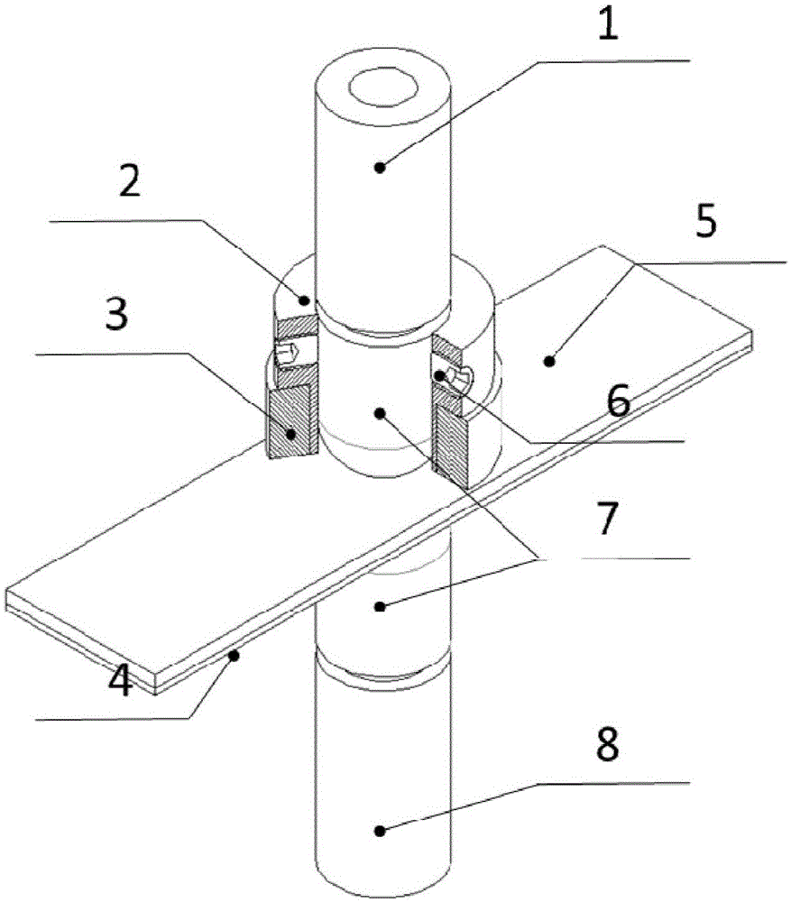
[0043] Such as figure 1 As shown, this embodiment includes: a ring-shaped permanent magnet 3, an insulating sleeve 2, an upper electrode rod 1 with an electrode cap 7 arranged sequentially on the thicker plate 5 from the outside to the inside, and an upper electrode rod 1 with an electrode cap 7 located under the thinner plate 4. The lower electrode rod 8 of the electrode cap 7, wherein: the annular permanent magnet 3 is coaxially socketed with the insulating sleeve 2, and the insulating sleeve 2 and the upper electrode rod 1 are fixedly connected by a positioning screw 6.

[0044] The outer diameters of the upper electrode rod 1 and the lower motor rod 8 are both 16mm.

[0045] The electrode cap 7 is a spherical flat electrode cap with an outer diameter of 16 mm and an end diameter of 5 mm.

[0046] The ring-shaped permanent magnet 3 has a magnetization direction perpendicular to the upper and lower plates; the ring-shaped permanent magnet 3 is a hollow cylinder with an inne...

Embodiment 2

[0064] The nugget shifting device of this embodiment is the same as that of Embodiment 1.

[0065] The upper plate 5 in this embodiment is 1.5mm austenitic stainless steel 301L, the lower plate 4 to be welded is 1.2mm duplex steel DP590; the electrode pressure is 3.5kN; the preloading time is 200ms, the welding time is 200ms, and The time is 100ms; the welding current is 5.5kA.

[0066] Other steps in this embodiment are the same as in Embodiment 1.

[0067] Such as Figure 8 As shown, the metallographic nugget evaluation standard after welding was tested, and the test results are listed in Table 2 below. The results show that the penetration depth of the low-resistivity side of the unilateral magnetron resistance spot welding is 0.375mm, the diameter of the nugget at the joint surface is 4.46mm, and the angle of the nugget at the low-resistivity side of the weak side is 32.3°; while the same welding Under the parameters, the traditional resistance spot welding with no exte...


PUM

PropertyMeasurementUnit
Outer diameteraaaaaaaaaa
End diameteraaaaaaaaaa
Wall thicknessaaaaaaaaaa

Abstract

The invention discloses a welding nuclear deviation control device and method for resistance spot welding. The welding nuclear deviation control device comprises a pair of electrode stems which are arranged on the outer sides of two plates to be welded respectively. An annular permanent magnet is arranged outside the electrode stem on any side. The annular permanent magnets are insulated from the electrode stems. The annular permanent magnets are arranged on the sides, with high specific resistance, of the two plates to be welded or on the sides, with large thicknesses, of the plates. According to the welding nuclear deviation control device and method, assembly and disassembly are convenient, and large-scale transformation over a production line is not needed; the externally-arranged annular permanent magnets can be used repeatedly, and thus application cost is low, and the device and method can be used for welding in a narrow space; magnetic field stirring is conducted during welding, in this way, welding nuclear deviation is weakened, crystal particles are refined and the directionality of the crystal particles is improved through the stirring action, composition segregation is eliminated, and the mechanical property of a spot-welded joint is further improved.

Description

technical field [0001] The present invention relates to a technique in the field of metal welding, in particular to a device and method for controlling offset of a resistance spot welding nugget. Background technique [0002] Energy saving and emission reduction is the theme of development in the world today. Lightweight vehicles can effectively improve energy utilization and reduce exhaust emissions, and the application of plates with different thicknesses and different strengths is an important way to lighten vehicles. According to statistics, the proportion of differential thickness and differential strength plate connections in the solder joints of automobile body-in-white has reached more than 60%. Therefore, it is of great significance to ensure the mechanical properties of differential thickness and differential strength plate resistance spot welding joints. However, when resistance spot welding is used to connect poorly thick plates, the heat dissipation intensity on...

Claims


Application Information

Patent Timeline
IPC IPC(8): B23K11/11B23K11/36B23K101/18B23K103/04
CPCB23K11/11B23K11/002B23K11/36B23K2101/18B23K2103/04
Inventor 李永兵李定泷张超群楼铭
Owner SHANGHAI JIAO TONG UNIV
Why Eureka
Try Eureka