
Plate plating hanger

An electroplating hanger and plate-type technology, which is applied in the electrolysis process and electrolytic components, etc., can solve the problems that the hanger deplating and pickling process is easily corroded, cannot be applied to small workpieces without hanging holes, and has a short service life. It is convenient and quick to put in or take out, save electroplating raw materials, and have high production efficiency.

Inactive Publication Date: 2016-10-19
SHENZHEN HUANXIANG FINISHING IND
View PDF4 Cites 0 Cited by
  • Summary
  • Abstract
  • Description
  • Claims
  • Application Information

AI Technical Summary

Problems solved by technology

Although the existing racks are widely used in electroplating because of their uniform coating and saving raw materials, their disadvantages are that not only the power consumption is large, but also the small workpieces without hanging holes cannot be used, and the racks are not suitable for the process of deplating and pickling. Susceptible to corrosion, short service life
In addition, the plated parts are hung or clamped on the support rod through the hook. During the electroplating process, it is easy to drop the plated parts into the electrolytic tank due to the looseness of the hook or the buoyancy of the plating solution when entering and exiting the tank, resulting in product scrap

Method used


Image

  • Plate plating hanger
  • Plate plating hanger
  • Plate plating hanger

Examples


Embodiment Construction

[0019] The following examples are further explanations and supplements to the present invention, and do not constitute any limitation to the present invention.

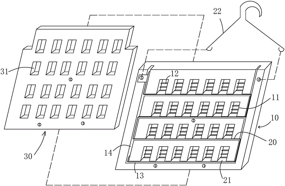
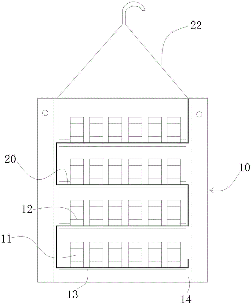
[0020] refer to figure 1 , The plate-type electroplating hanger of the present invention includes a plate-shaped base 10 , a metal cathode 20 and a cover plate 30 .

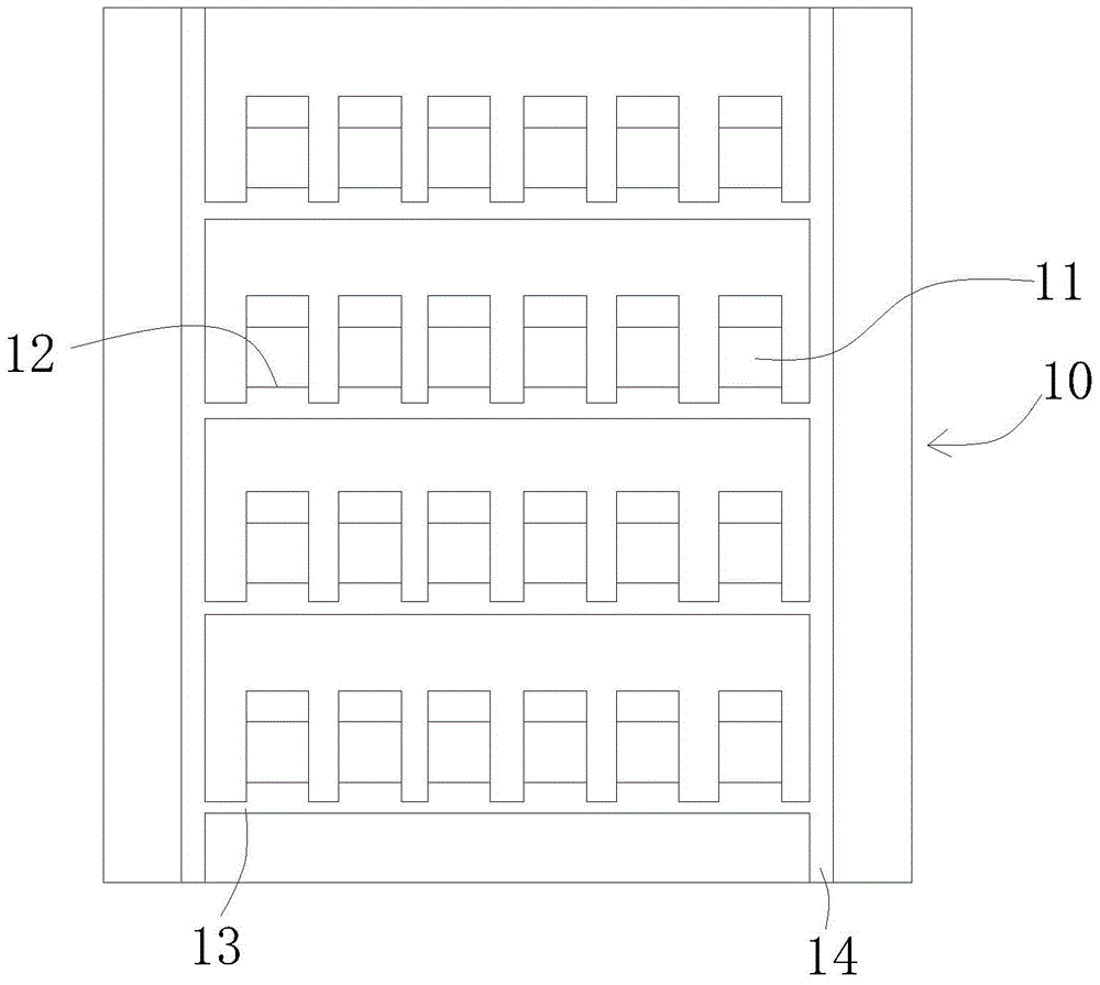
[0021] Such as figure 1 , figure 2 As shown, the plate base 10 is made of insulating material, and the plate base 10 may be made of polypropylene material, polyethylene material or other chemically stable insulating materials. In this embodiment, the plate base 10 is made of polypropylene material. Grid-like plating holes 11 are arranged on the plate base 10, and the plating holes 11 are arranged in multiple rows and columns at intervals. In this embodiment, the plating holes 11 are arranged in four rows and six columns at intervals. Each plated part hole 11 runs through from one side of the plate-shaped substrate 10 to the other side, and its cross...


PUM


Abstract

The invention discloses a plate type electroplating hanger. The hanger comprises a plate-shaped base body made of insulating materials. The plate-shaped base body is provided with a plurality of rows of grid-shaped electroplating piece holes and a plurality of lines of grid-shaped electroplating piece holes arranged at intervals. The electroplating piece holes are communicated to the other face of the plate-shaped base body from one face of the plate-shaped base body. The plate-shaped base body is provided with a metal cathode. The metal cathode rotates and surrounds each row of electroplating piece holes to the tail ends of the electroplating piece holes in the last row from the first row of electroplating piece holes. One part of the metal cathode is embedded in the electroplating piece holes in an exposed manner. The tail end of the metal cathode is electrically connected with an electric conduction hook. By means of the plate type electroplating hanger, a plurality of small components can be electroplated at the same time, and electroplated products are even in electroplating layer, low in energy consumption, high in production efficiency and the like. The plate type electroplating hanger further has the beneficial effects of being simple in structure, capable of achieving energy saving and environment friendliness, convenient to machine and the like.

Description

【Technical field】 [0001] The invention relates to an electroplating appliance, in particular to a plate-type electroplating rack capable of simultaneously electroplating a plurality of small parts and having high production efficiency. 【Background technique】 [0002] In industrial production, a large number of products require surface treatment to make them better in use. When performing functional electroplating on workpieces that are small in size, thin, light, and without hanging holes, methods such as barrel plating, tie plating, plated mesh plating, and rack plating are usually used. However, for small and light workpieces, barrel plating will cause poor electrical conductivity and bubbles due to the lightness of the workpiece, which is easy to float in the plating solution. At the same time, scratches are easily formed on the surface of the coating, which affects the quality of the coating; In addition, when the plated mesh is used for electroplating, the plated parts...

Claims


Application Information

Patent Timeline
Patent Type & Authority Patents(China)
IPC IPC(8): C25D17/08
Inventor 董有光陈卫星王秀华薛瑶香
Owner SHENZHEN HUANXIANG FINISHING IND
Learn More