Multilane laser light plane calibration method based on binocular vision

A multi-line laser, binocular vision technology, applied in the field of image processing and visual measurement, can solve the problems of small number of calibration points, positioning accuracy susceptible to camera distortion, difficult to obtain calibration accuracy, etc., to achieve high calibration accuracy and improve practicality. sexual effect

Inactive Publication Date: 2015-11-25
NANJING UNIV OF POSTS & TELECOMM
View PDF4 Cites 31 Cited by
  • Summary
  • Abstract
  • Description
  • Claims
  • Application Information

AI Technical Summary

Problems solved by technology

Since the calibration points are not feature points directly extracted from the image, its positioning accuracy is easily affected by camera distortion, etc., and the number of calibration points obtained is not large, especially the method of obtaining calibration points based on the principle of double cross-ratio invariance, the first The error caused by the constant cross ratio of the second time will also propagate to the second cross ratio, resulting in error accumulation, so it is not easy to obtain high calibration accuracy

Method used


Image

  • Multilane laser light plane calibration method based on binocular vision
  • Multilane laser light plane calibration method based on binocular vision
  • Multilane laser light plane calibration method based on binocular vision

Examples


Embodiment Construction

[0055] Below in conjunction with accompanying drawing, technical scheme of the present invention is described in further detail:

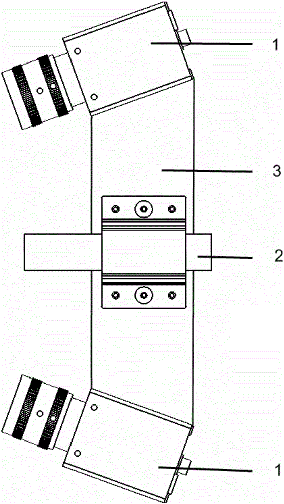
[0056] figure 1 Shown is the multi-laser line scanning device used in the implementation of the present invention, which consists of left and right eye cameras and a multi-line laser emitter. Both the left and right eye cameras use the DMK23U445 industrial camera from TheImagingSource Company, the sensor is 1 / 3"CCD, the output mode is USB3.0, and the lens uses ComputarM0814-MP2 megapixel fixed-focus lens. The two cameras are rigidly connected by the skeleton, and the left and right eye cameras The angle between the optical axes is about 40°, and the baseline distance is about 25cm. The multi-line laser is located in the middle of the two cameras and emits 5 parallel beams.

[0057] Such as figure 2 Shown is a schematic diagram of the target of the present invention. There are 5 rows and 6 columns of circular marking points distributed on the tar...


PUM


Abstract

The invention discloses a multilane laser light plane calibration method based on binocular vision. The method comprises the following steps: projecting laser rays emit by the multilane laser onto a plane calibration target having circular markers, and guaranteeing that the laser rays are distributed at intervals between rows of the circular markers; processing calibration target images shoot by the left and the right eye camera and obtaining a stereo matching of the pixel of the marker center, and then extracting and separating laser pixel points of different laser rays; using the theory of binocular vision to calculate the three-dimensional coordinates of the marker center and subsequently obtaining a calibration target plane equation; calculating the three-dimensional coordinates with the calibration target plane equation as restraints; moving the calibration target and repeating the aforementioned procedure at least once, and obtaining the three-dimensional coordinates of different positions on each light plane; fitting the multiple position data points on each light plane and obtaining a light plane equation. According to the invention, the method is characterized by easy implementation, linear solution and reliable result, and is applicable to all fields which employ multilane structured light in three-dimensional measurement.

Description

technical field [0001] The invention relates to a multi-line laser optical plane calibration method based on binocular vision, which belongs to the field of image processing and visual measurement. Background technique [0002] Visual measurement is a technology that uses a camera to collect images of the surface of the object being measured and restores the three-dimensional shape of the object to be measured from it. Among many visual measurement methods, the line structured light measurement method with laser line as the realization method has been widely used because of its good measurement accuracy and good adaptability to the surface color of objects. The measurement method based on the single-line laser can only obtain the data of one section line on the surface of the object at a time, which has the defect of low measurement efficiency. One solution to overcome the above drawbacks is to use multi-line lasers for measurement. [0003] Accurate calibration of multi-l...

Claims


Application Information

Patent Timeline
Patent Type & Authority Applications(China)
IPC IPC(8): G01B11/24G06T7/00
Inventor 聂建辉刘烨
Owner NANJING UNIV OF POSTS & TELECOMM
Why Eureka
Try Eureka