Piezoelectric acceleration sensor signal conversion circuit excited by current source

A piezoelectric acceleration, sensor signal technology, applied in the direction of acceleration measurement using inertial force, can solve the problems of difficult to adjust the static operating point, static operating point will drift, etc., to achieve simple structure, convenient connection, good temperature stability Effect

Active Publication Date: 2015-11-25
NANJING FORESTRY UNIV
View PDF4 Cites 5 Cited by
  • Summary
  • Abstract
  • Description
  • Claims
  • Application Information

AI Technical Summary

Problems solved by technology

Although the input resistance between the gate and source of the junction field effect transistor can reach more than MΩ, it is not very high; the gate-source voltage of the amplifier circuit is negative in static operation, it is difficult to adjust the static operating point, and the junction field effect The temperature stability of the tube is not as good as the insulated gate field effect tube, and the static operating point will drift

Method used


Image

  • Piezoelectric acceleration sensor signal conversion circuit excited by current source
  • Piezoelectric acceleration sensor signal conversion circuit excited by current source

Examples


Embodiment Construction

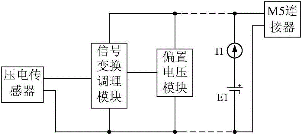
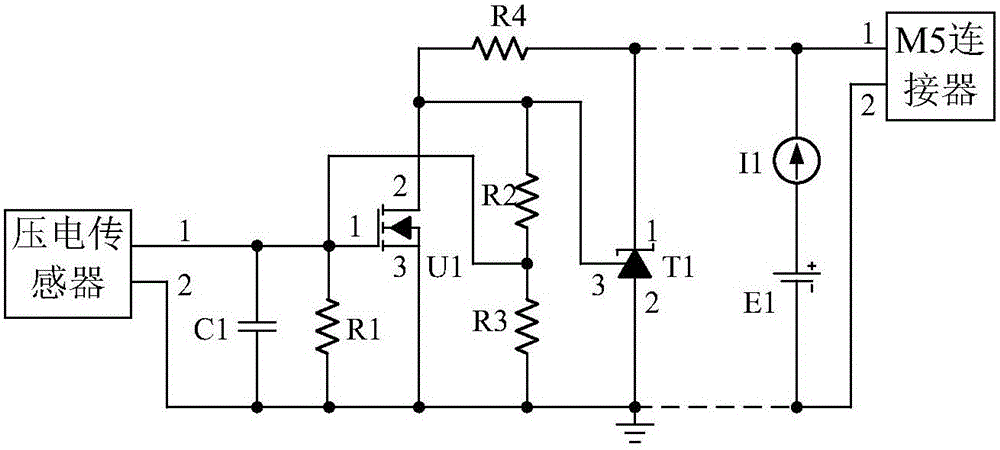
[0018] attached figure 1 And attached figure 2 It is a structural block diagram and principle diagram of a piezoelectric acceleration sensor signal conversion circuit excited by a current source provided by an embodiment of the present invention. It mainly includes a bias voltage module and a signal conversion and conditioning module. E1 and I1 are external excitation sources, and I1 usually adopts the internationally accepted 4~20mA. The dotted line in the figure indicates that the long-distance cable connects the output of the circuit with the external excitation source, sharing the same M5 connector. Terminal 1 of the three-terminal precision adjustable reference source T1 is respectively connected to one terminal of the resistor R4 and terminal 1 of the M5 connector; terminal 2 of T1 is respectively connected to the ground and terminal 2 of the M5 connector. Terminal 3 of T1 is connected to terminal 2 of IGSFET U1, and at the same time connected to the other end of res...


PUM


Abstract

The present invention provides a piezoelectric acceleration sensor signal conversion circuit excited by a current source, comprising a bias voltage module and a signal conversion regulation module. The circuit provided by the invention has a self-reference voltage provided by a precise voltage source, and the self-reference voltage is divided by a resistor so as to generate a quiescent operating point of an insulated gate field-effect tube; and alternating quantities of electric charges are overlaid on the quiescent operating point, the electric charges are changed to current through the insulated gate field-effect tube, and voltage signals corresponding to the alternating electric charges are obtained through conversion of the resistor. With good stability of the temperature, simple structure of the circuit, few elements and low cost, the circuit provided by the invention is easy to regulate the quiescent operating point of the conversion circuit, may work without impressed voltage sources, and is provided with the same interface and only two wires for inputting and outputting signals, therefore facilitating to connect with external circuits and improving the reliability. Moreover, the current signals flow within the interface so as to be used for a long distance measurement, therefore having a great extensive value in use.

Description

technical field [0001] The invention relates to a circuit for converting the high input impedance of the sensor into a low input impedance in the field of piezoelectric acceleration sensor detection, realizing the conversion of the output charge of the sensor, and the conversion of the current to the voltage signal. Background technique [0002] The piezoelectric acceleration sensor uses the piezoelectric effect to measure non-electric physical quantities such as vibration and impact. For example, in the field of magnetic suspension bearings, the piezoelectric acceleration sensor is used to obtain the data after the rotor is excited by the hammer, and analyze the model of the rigid body of the rotor. State mode; In the non-destructive testing technology of forestry trees, the piezoelectric acceleration sensor picks up the mechanical stress wave vibration waveform of the knock, detects and calculates the propagation speed of the stress wave to analyze the elastic modulus of th...

Claims


Application Information

Patent Timeline
Patent Type & Authority Applications(China)
IPC IPC(8): G01P15/09
Inventor 王军赵茂程黄聪周国平徐磊邹明哲
Owner NANJING FORESTRY UNIV
Why Eureka
Try Eureka